
Vehicle positioning method, vehicle positioning device and terminal equipment

A vehicle positioning and vehicle technology, which is applied in the field of vehicle navigation, can solve the problems that the navigation system is difficult to provide precise vehicle positioning, interference, and navigation satellite signals are easily lost and locked.

Inactive Publication Date: 2019-06-07
LAUNCH TECH CO LTD
View PDF6 Cites 25 Cited by
  • Summary
  • Abstract
  • Description
  • Claims
  • Application Information

AI Technical Summary

Problems solved by technology

[0002] In the process of the vehicle's navigation system navigating the route for the vehicle, the global positioning system GPS for positioning the vehicle itself needs to calculate the position and speed of the vehicle based on the received navigation satellite signals, and the above-mentioned navigation satellite signals are in tunnels, underground garages, etc. In special scenarios such as ring viaducts and ring viaducts, it is easy to lose the lock and be easily interfered by external signals, making it difficult for the vehicle's navigation system to provide accurate positioning of the vehicle; while the navigation error of the inertial navigation INS continues to accumulate over time, making it difficult to provide Long-term positioning accuracy

Method used


Image

  • Vehicle positioning method, vehicle positioning device and terminal equipment
  • Vehicle positioning method, vehicle positioning device and terminal equipment
  • Vehicle positioning method, vehicle positioning device and terminal equipment

Examples


Embodiment 1

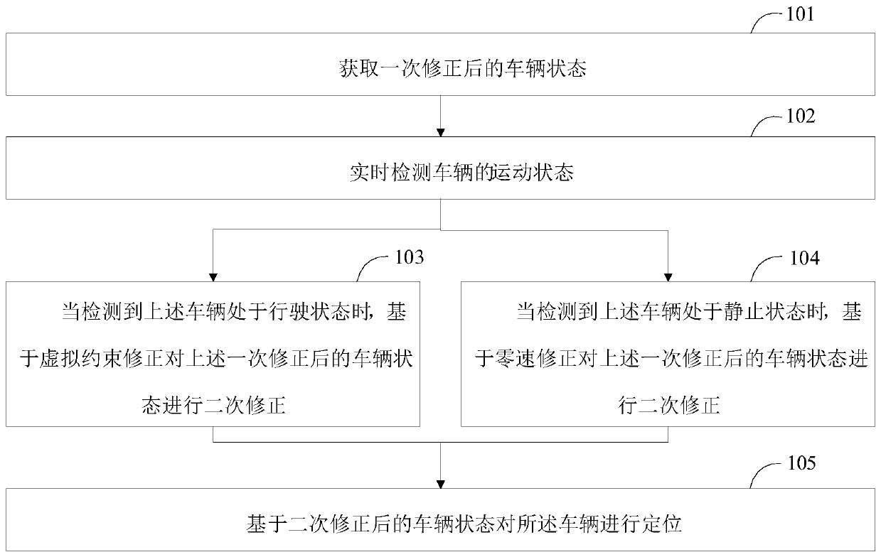
[0065] A vehicle positioning method provided in an embodiment of the present application is described below. see figure 1 , the vehicle positioning method in the embodiment of the present application includes:

[0066] In step 101, the vehicle state after correction is obtained once;

[0067] In the embodiment of the present application, the vehicle state after a correction of the vehicle is first obtained, wherein the vehicle state includes the speed, position, orientation and attitude of the vehicle. Optionally, the above step 101 includes:

[0068] Step A1. In the static state of the vehicle, perform online calibration and error compensation on the inertial sensor of the vehicle, so as to realize real-time correction of the output data of the gyroscope and accelerometer in the inertial sensor, and complete the initialization of the zero bias data of the above gyroscope ;

[0069] Step A2, in the straight-line driving state of the vehicle, perform initial alignment on th...

Embodiment 2

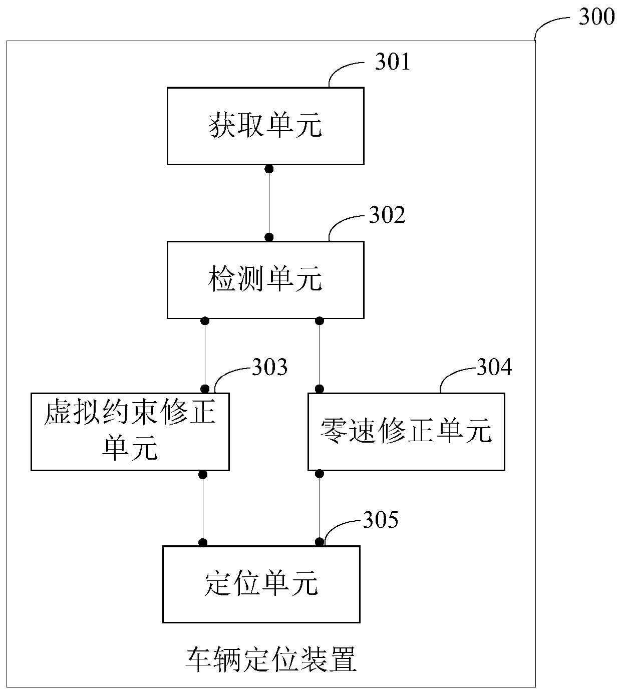
[0132] The embodiment of the present application provides a vehicle positioning device, such as image 3 As shown, the vehicle positioning device 300 in the embodiment of the present application includes:

[0133] An acquisition unit 301, configured to acquire a corrected vehicle state, wherein the vehicle state includes speed, position, orientation and attitude;

[0134] A detection unit 302, configured to detect the motion state of the vehicle in real time;

[0135] A virtual constraint correction unit 303, configured to, when it is detected that the vehicle is in a driving state, perform a secondary correction on the vehicle state after the primary correction based on the virtual constraint correction;

[0136] A zero-speed correction unit 304, configured to perform a secondary correction on the vehicle state after the primary correction based on the zero-speed correction when the above-mentioned vehicle is detected to be in a stationary state;

[0137] The positioning unit...

Embodiment 3

[0158] Figure 4 It shows a schematic structural diagram of a terminal device provided by an embodiment of the present application. The terminal device 4 of this embodiment includes: a processor 40, a memory 41, and a computer program stored in the memory 41 and operable on the processor 40 42. For example, the vehicle positioning program in the vehicle positioning method. When the above-mentioned processor 40 executes the above-mentioned computer program 42, the steps in the above-mentioned embodiments of the vehicle positioning method are realized, for example figure 1 Steps S101 to 105 are shown.

[0159] The above-mentioned terminal device 4 may include, but not limited to, a processor 40 and a memory 41 . Those skilled in the art can understand that, Figure 4 It is only an example of the terminal device 4, and does not constitute a limitation to the terminal device 4. It may include more or less components than those shown in the illustration, or combine some componen...


PUM


Abstract

The application discloses a vehicle positioning method, a vehicle positioning device, terminal equipment and a computer readable storage medium. The vehicle positioning method comprises the followingsteps that a vehicle state after primary correction is acquired, wherein the vehicle state comprises speed, position, orientation and posture; the motion state of a vehicle is detected in real time; when the vehicle is detected in a running state, secondary correction is carried out on the vehicle state after the primary correction based on virtual constraint correction; when the vehicle is detected is in a stationary state, secondary correction is carried out on the vehicle state after the primary correction based on zero speed correction; and the vehicle is positioned based on the vehicle state after secondary correction. According to the scheme of the vehicle positioning method, the vehicle positioning device, the terminal equipment and the computer readable storage medium, on the premise of accurately judging the running state of the vehicle, parameters such as speed, position, orientation, posture and the like of the vehicle are correspondingly corrected according to different moving states of the vehicle, so that the positioning accuracy of the vehicle is improved.

Description

technical field [0001] The present application belongs to the technical field of vehicle navigation, and in particular relates to a vehicle positioning method, a vehicle positioning device, a terminal device and a computer-readable storage medium. Background technique [0002] In the process of the vehicle's navigation system navigating the route for the vehicle, the global positioning system GPS for positioning the vehicle itself needs to calculate the position and speed of the vehicle based on the received navigation satellite signals, and the above-mentioned navigation satellite signals are in tunnels, underground garages, etc. In special scenarios such as ring viaducts and ring viaducts, it is easy to lose the lock and be easily interfered by external signals, making it difficult for the vehicle's navigation system to provide accurate positioning of the vehicle; while the navigation error of the inertial navigation INS continues to accumulate over time, making it difficul...

Claims


Application Information

Patent Timeline
Patent Type & Authority Applications(China)
IPC IPC(8): G01C21/16G01C21/28G01C25/00G01S19/47
Inventor 刘新褚之恒蔡晓彬
Owner LAUNCH TECH CO LTD
Learn More