Multi-condition fatigue test system for tread brake unit
A tread braking and fatigue test technology, applied in the field of fatigue test systems, can solve the problems of single type, single test bench simulation conditions, and inability to more realistically simulate the combined conditions of existing vehicles, etc., to achieve compact structure and short fatigue test time Effect
- Summary
- Abstract
- Description
- Claims
- Application Information
AI Technical Summary
Problems solved by technology
Method used
Image
Examples
Embodiment 1
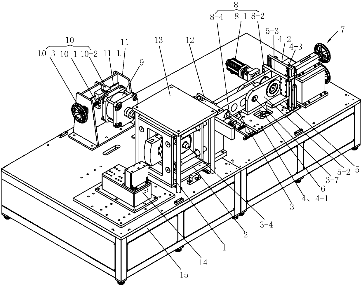
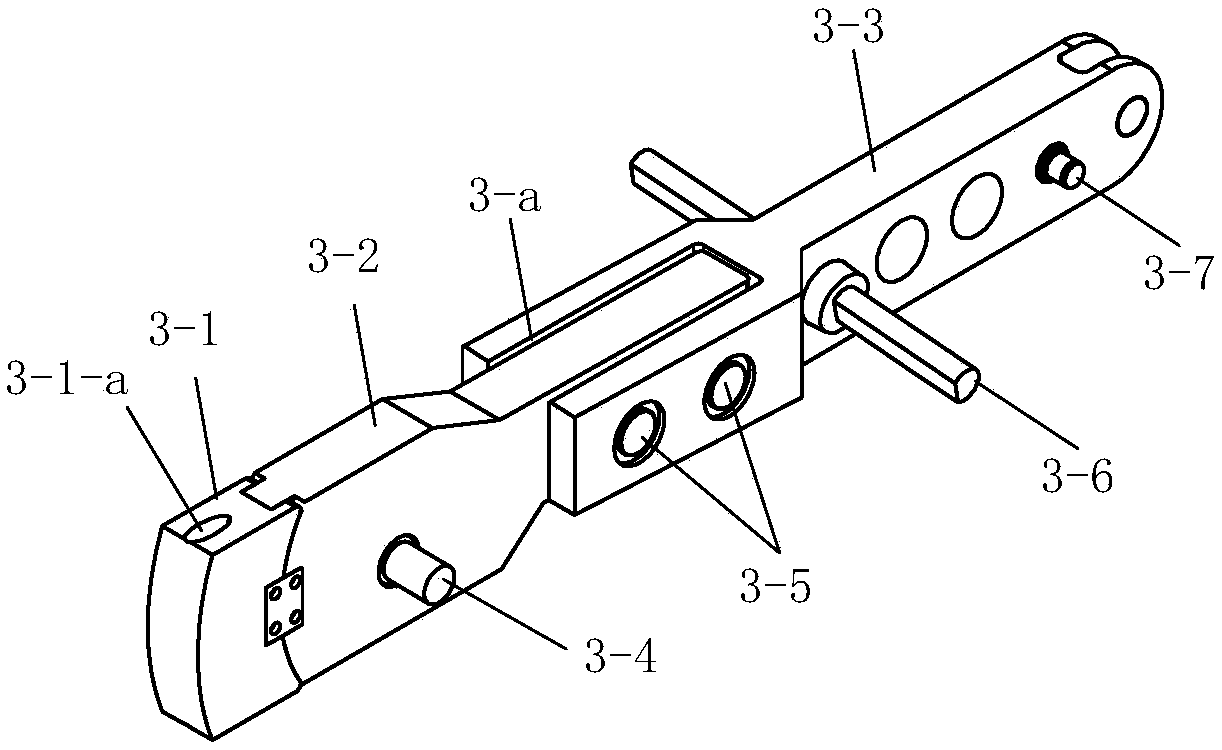
[0027] See Figure 1 to Figure 8 , this embodiment includes a test platform 15, a front support frame 1 and a rear support frame 4 arranged on the front and rear sides of the test platform 15, and a fixing seat 11 arranged on the side of the front support frame 1, and a tread profiling module is also provided 3. Tangential force application cylinder 6, longitudinal adjustment device 7, reciprocating vibration cam mechanism 8, and lateral force application cylinder 9.
[0028] A pair of transverse guide rails 15-1 are fixed on the front side of the test platform 15, and a pair of longitudinal guide rails 15-2 are fixed on the rear side.
[0029] The front support frame 1 is movably connected to the transverse guide rail 15-1 by means of a slide block on the bottom surface. The front support frame 1 is provided with a slide frame 2, and four longitudinal guide columns 1-1 distributed in pairs are installed in the front support frame 1, and the slide frame 2 is worn on the four ...
Embodiment 2
[0043] The longitudinal adjustment device 7 is provided with a second transmission mechanism 7-2, the movable part of the second transmission mechanism 7-2 is directly below the movable part of the first transmission mechanism 7-1, and the activity of the second transmission mechanism 7-2 Part is connected with the riser 4-2 of rear support frame 4. The two transmission mechanisms run synchronously. All the other are identical with embodiment 1.
[0044] When the test system is in use, the tread unit brake is installed on the tooling 14, and the first transmission mechanism 7-1 and the second transmission mechanism 7-2 of the longitudinal adjustment device 7 are manually operated synchronously to drive the rear support frame 4 to move, so that the lifting seat 5 Drive the tread profiling module 3 to move, so that the profiling tread head 3-1 is in contact with the tread unit brake. Since the sliding frame 2 also moves with the tread profiling module 3, the lateral force exert...
PUM
 Abstract
Description
Claims
Application Information
 - R&D Engineer
- R&D Manager
- IP Professional
- Industry Leading Data Capabilities
- Powerful AI technology
- Patent DNA Extraction
Browse by: Latest US Patents, China's latest patents, Technical Efficacy Thesaurus, Application Domain, Technology Topic, Popular Technical Reports.
© 2024 PatSnap. All rights reserved.Legal|Privacy policy|Modern Slavery Act Transparency Statement|Sitemap|About US| Contact US: help@patsnap.com


