Small lens and under-screen optical assembly

A technology of optical components and lenses, applied in optical components, optics, installation, etc., can solve problems such as difficult screen-to-body ratio and large size, and achieve the effect of improving screen-to-body ratio

Inactive Publication Date: 2019-06-07
TRULY OPTO ELECTRONICS
View PDF3 Cites 18 Cited by
  • Summary
  • Abstract
  • Description
  • Claims
  • Application Information

AI Technical Summary

Problems solved by technology

[0002] With the development of full screen technology, more and more mobile phones start to use full screen, because the display screen will affect the imaging of the camera, such as figure 1 As shown, the existing under-display optical assembly will set up an avoidance groove / hole 21' on the display screen 2' to accommodate the lens 1', and the light incident end of the lens 1' will extend into the avoidance groove / hole 21' of the display screen 2' In the hole 21', at this time, the size of the avoidance groove / hole 21' depends on the size of the light-incident end of the lens 1', and the size of the light-incident end of the lens 1' includes the size of the light-incident lens 12a' located at the light-incident end. Due to the size and the thickness of the lens barrel 11', the size of the avoidance groove / hole 21' opened on the display screen 2' is relatively large, making it difficult to further increase the screen-to-body ratio

Method used


Image

  • Small lens and under-screen optical assembly
  • Small lens and under-screen optical assembly
  • Small lens and under-screen optical assembly

Examples


Embodiment 1

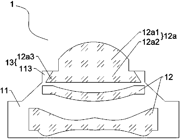
[0022] like figure 2 As shown, a small lens 1 includes a lens barrel 11 and a plurality of optical lenses 12 arranged in the lens barrel 11 along the optical axis direction, and the plurality of optical lenses 12 include an entrance lens located in the lens barrel 11. The incident lens 12a at the light end; the incident lens 12a includes a fixed part 12a2 and a protruding part 12a1 connected along the optical axis direction, the fixed part 12a2 is installed in the lens barrel 11, and the protruding part 12a1 is higher than the light incident end surface of the lens barrel 11 , and the diameter of the protrusion 12a1 is smaller than the outer diameter of the light incident end of the lens barrel 11 .

[0023] The small lens 1 protrudes the light incident lens 12a located at the light incident end, so that it is higher than the light incident end face of the lens barrel 11 and has a diameter smaller than the light incident end outer diameter of the lens barrel 11, so that The ...

Embodiment 2

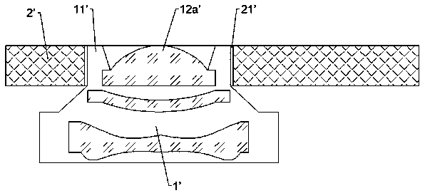
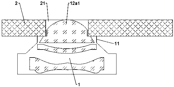
[0029] like image 3 As shown, an under-screen optical assembly includes a display screen 2 with an avoidance groove / hole 21 and the small lens 1 described in Embodiment 1, the small lens 1 is arranged on the back of the display screen 2 and inserted into the The protruding portion 12a1 of the light lens 12a extends into the avoidance groove / hole 21 of the display screen 2, and the light-incident end face of the lens barrel 11 is against the periphery of the display screen 2 at the avoidance groove / hole 21. back.

[0030] Preferably, the light-incident end face of the lens barrel 11 is bonded and fixed to the peripheral back surface of the display screen 2 at the avoidance groove / hole 21 through an adhesive, and the adhesive is acrylic or epoxy. The highly transparent adhesive material such as resin can be but not limited to OCA glue.

[0031] The avoidance groove / hole 21 can be a side groove set outside the display area of ​​the display screen 2, that is, the display screen...


PUM


Abstract

The invention discloses a small lens and an under-screen optical assembly. The small lens comprises a mirror tube and a plurality of optical lenses arranged in the mirror tube in the optical axis direction, and the multiple optical lenses comprise light inlet lenses located at the light inlet end of the mirror tube; each light inlet lens comprises a fixed part and a bulged part which are connectedin the optical axis direction, and the fixed parts are mounted in the mirror tube; and the bulged parts are higher than the end face of the light inlet end of the mirror tube, and the diameter of thebulged parts is less than the outer diameter of the light inlet end of the mirror tube. The small lens can further increase the screen-to-body ratio of the under-screen optical assembly.

Description

technical field [0001] The invention relates to under-screen optical technology, in particular to a small lens and an under-screen optical component. Background technique [0002] With the development of full screen technology, more and more mobile phones start to use full screen, because the display screen will affect the imaging of the camera, such as figure 1 As shown, the existing under-display optical components will have an avoidance groove / hole 21' on the display screen 2' to accommodate the lens 1', and the light incident end of the lens 1' will extend into the avoidance groove / hole 21' of the display screen 2' In the hole 21', at this time, the size of the avoidance groove / hole 21' depends on the size of the light-incident end of the lens 1', and the size of the light-incident end of the lens 1' includes the size of the light-incident lens 12a' at the light-incident end. Due to the size and the thickness of the lens barrel 11', the size of the escape groove / hole 21...

Claims


Application Information

Patent Timeline
Patent Type & Authority Applications(China)
IPC IPC(8): G02B7/02G02B13/00G03B30/00
Inventor 王富民
Owner TRULY OPTO ELECTRONICS
Why Eureka
Try Eureka