Eureka AIR delivers breakthrough ideas for toughest innovation challenges, trusted by R&D personnel around the world.

JFET device and manufacturing method thereof

A manufacturing method and device technology, which are applied in semiconductor/solid-state device manufacturing, semiconductor devices, electrical components, etc., can solve the problems of difficult adjustment, increased device area, and high pinch-off voltage.

Pending Publication Date: 2019-06-07
福州臻美网络科技有限公司
View PDF0 Cites 3 Cited by
  • Summary
  • Abstract
  • Description
  • Claims
  • Application Information

AI Technical Summary

Problems solved by technology

[0004] Because the junction depth of the non-epitaxial LJFET channel region is too deep, it is difficult to pinch off the JFET, the pinch-off voltage is usually high, and it is not easy to adjust
In order to reduce the pinch-off voltage, the method of lengthening the JFET channel is usually adopted, and in doing so, the area of ​​the device is greatly increased, and the integration of the chip is sacrificed.

Method used


Image

  • JFET device and manufacturing method thereof
  • JFET device and manufacturing method thereof
  • JFET device and manufacturing method thereof

Examples


Embodiment Construction

[0014] In order to make the objectives, technical solutions and beneficial technical effects of the present invention clearer, the technical solutions in the embodiments of the present invention will be clearly and completely described below in conjunction with the drawings in the embodiments of the present invention. Obviously, the described implementation Examples are only some embodiments of the present invention, not all embodiments. Based on the embodiments of the present invention, all other embodiments obtained by persons of ordinary skill in the art without making creative efforts belong to the protection scope of the present invention.

[0015] In the description of the present invention, it should be noted that the terms "center", "upper", "lower", "left", "right", "vertical", "horizontal", "inner", "outer" etc. The indicated orientation or positional relationship is based on the orientation or positional relationship shown in the drawings, or the orientation or posi...


PUM


Abstract

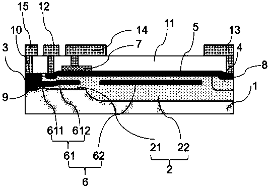
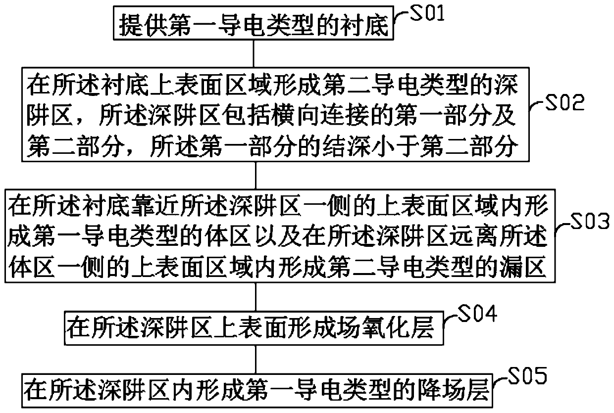
The invention relates to the technical field of semiconductors, and in particular relates to a JFET device and a manufacturing method thereof. The method comprises steps: a substrate of a first conductive type is provided; a deep well area of a second conductive type is formed on the upper surface area of the substrate, wherein the deep well area comprises a first part and a second part which aretransversely connected, and the junction depth of the first part is smaller than that of the second part; the upper surface area, close to one side of the deep well area, of the substrate is internally provided with a body area of a first conductive type, and the upper surface area, far away from one side of the body area, of the deep well area is internally provided with a drain area of a secondconductive type; a field oxide layer is formed on the upper surface of the deep well area; and a reduced-field layer of a first conductive type is formed in the deep well area. The JFET device formedin the above method withstands high voltage, and the area is small.

Description

technical field [0001] The invention relates to the technical field of semiconductors, in particular to a JFET device and a manufacturing method thereof. Background technique [0002] In power application equipment, JFET (Junction Field-Effect Transistor, Junction Field-Effect Transistor), JFET is a three-terminal active device with amplification function composed of p-n junction gate, source and drain. The principle is to control the output current by changing the conductivity of the channel through the voltage. [0003] According to its conductive path, JFET can also be divided into VJFET and LJFET. The conductive path of LJFET is horizontal, and the source and drain are distributed on the front side of the substrate. However, the conduction path of VJFET is vertical, and the drain terminal is often arranged on the backside of the substrate. Since lateral LJFET devices are easier to integrate with traditional CMOS processes, they are often integrated into CMOS circuits a...

Claims


Application Information

Patent Timeline
Patent Type & Authority Applications(China)
IPC IPC(8): H01L29/10H01L21/337H01L29/808
Inventor 不公告发明人
Owner 福州臻美网络科技有限公司
Why Eureka
Eureka Blog
Learn More