
Electrical connector

An electrical connector and electrical connection technology, applied in the direction of the base/shell, etc., can solve the problems affecting the assembly and electrical conduction of the electrical connector, and achieve the effect of reducing the production scrap rate and production cost.

Pending Publication Date: 2019-06-07
株洲时代龙友科技有限公司
View PDF0 Cites 0 Cited by
  • Summary
  • Abstract
  • Description
  • Claims
  • Application Information

AI Technical Summary

Problems solved by technology

[0003] The purpose of the present invention is to provide an electrical connector, aiming at solving the problem that the rubber material is easily injected into the mating part of the electrical connector during the rubber encapsulation process in the prior art, which affects the assembly and electrical connection of the electrical connector in the later stage. Conduction problem

Method used


Image

  • Electrical connector
  • Electrical connector
  • Electrical connector

Examples


Embodiment Construction

[0024] In order to make the object, technical solution and advantages of the present invention clearer, the present invention will be further described in detail below in conjunction with the accompanying drawings and embodiments. It should be understood that the specific embodiments described here are only used to explain the present invention, not to limit the present invention.

[0025] It should be noted that when an element is referred to as being “fixed on” or “disposed on” another element, it may be directly on the other element or there may be an intervening element at the same time. When an element is referred to as being "connected to" another element, it can be directly connected to the other element or intervening elements may also be present.

[0026] It should also be noted that the orientation terms such as left, right, up, and down in this embodiment are only relative concepts or refer to the normal use state of the product, and should not be regarded as limiti...


PUM


Abstract

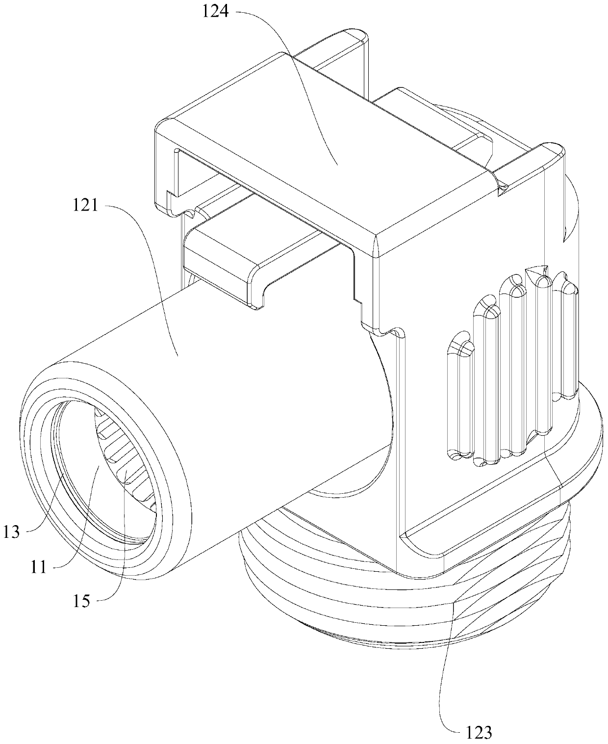
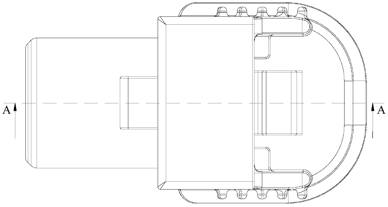
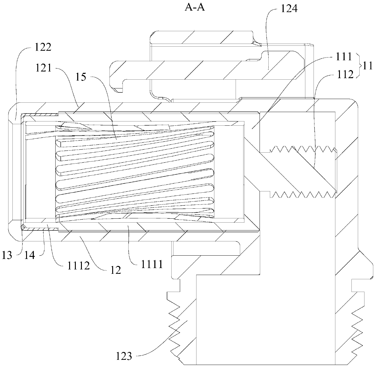
The invention relates to the technical field of electrical connectors, and provides an electrical connector. The electrical connector comprises a conductive sleeve, an encapsulating outer casing and amaterial blocking ring. The conductive sleeve comprises an insertion portion and a wiring portion, one end of the insertion portion is provided with an insertion hole, and the other end of the insertion portion is electrically connected with the wiring portion; the encapsulating outer casing comprises a housing main body and an anti-off snap ring, one side of the housing main body is provided with an insertion holding hole, the other side thereof is provided with a wiring holding hole, and the anti-off snap ring is formed by extending inwards from the port edge of the hole port of the insertion holding hole. The electrical connector further comprises a material blocking ring arranged in the insertion holding hole and located between the anti-off snap ring and the insertion portion, wherein the inner ring diameter of the material blocking ring is smaller than the hole diameter of the insertion hole. The electrical connector is provided with the material blocking ring at the insertion hole of the conductive sleeve to block an insulation material from being incident to a matching portion of the conductive sleeve in the late process for forming the encapsulating outer casing so as toguarantee the assembling and electrical connection conduction of the conductive sleeve and a plug pin in the late phase without the influence of the insulation material.

Description

technical field [0001] The invention relates to the technical field of electrical connectors, in particular to an electrical connector structure. Background technique [0002] In recent years, electrical connectors have been widely used in various electrical circuits to play the role of connecting or disconnecting circuits. In the manufacturing process of electrical connectors, it is often necessary to go through a process: to form a plastic covering shell on the surface through the plastic covering injection molding process to play the role of electrical insulation. Injection into the mating part of the electrical connector will have a greater impact on the later assembly and electrical conduction of the electrical connector. Contents of the invention [0003] The object of the present invention is to provide an electrical connector, aiming at solving the problem that the rubber material is easy to inject into the mating part of the electrical connector when the electric...

Claims


Application Information

Patent Timeline
IPC IPC(8): H01R13/46
Inventor 乐龙兵黎鹏
Owner 株洲时代龙友科技有限公司
Learn More