
Switching power supply capacitor charging circuit and charging method

A switching power supply, capacitor charging technology, applied in battery circuit devices, circuit devices, current collectors, etc., can solve the problems of inability to pump capacitor charging and low driving efficiency.

Pending Publication Date: 2019-06-07
GUANGZHOU XAIRCRAFT TECH CO LTD
View PDF0 Cites 1 Cited by
  • Summary
  • Abstract
  • Description
  • Claims
  • Application Information

AI Technical Summary

Problems solved by technology

[0004] In view of this, the embodiment of the present invention provides a switching power supply capacitor charging circuit and charging method to solve the problem that the existing pumping capacitor charging circuit of the switching power supply cannot charge the pumping capacitor before the switching power supply control circuit is started. The problem of low drive efficiency

Method used


Image

  • Switching power supply capacitor charging circuit and charging method
  • Switching power supply capacitor charging circuit and charging method
  • Switching power supply capacitor charging circuit and charging method

Examples


Embodiment Construction

[0026] The technical solutions of the present invention will be clearly and completely described below in conjunction with the accompanying drawings. Apparently, the described embodiments are some of the embodiments of the present invention, but not all of them. Based on the embodiments of the present invention, all other embodiments obtained by persons of ordinary skill in the art without making creative efforts belong to the protection scope of the present invention.

[0027] In the description of the present invention, it should be noted that the terms "center", "upper", "lower", "left", "right", "vertical", "horizontal", "inner", "outer" etc. The indicated orientation or positional relationship is based on the orientation or positional relationship shown in the drawings, and is only for the convenience of describing the present invention and simplifying the description, rather than indicating or implying that the referred device or element must have a specific orientation, ...


PUM


Abstract

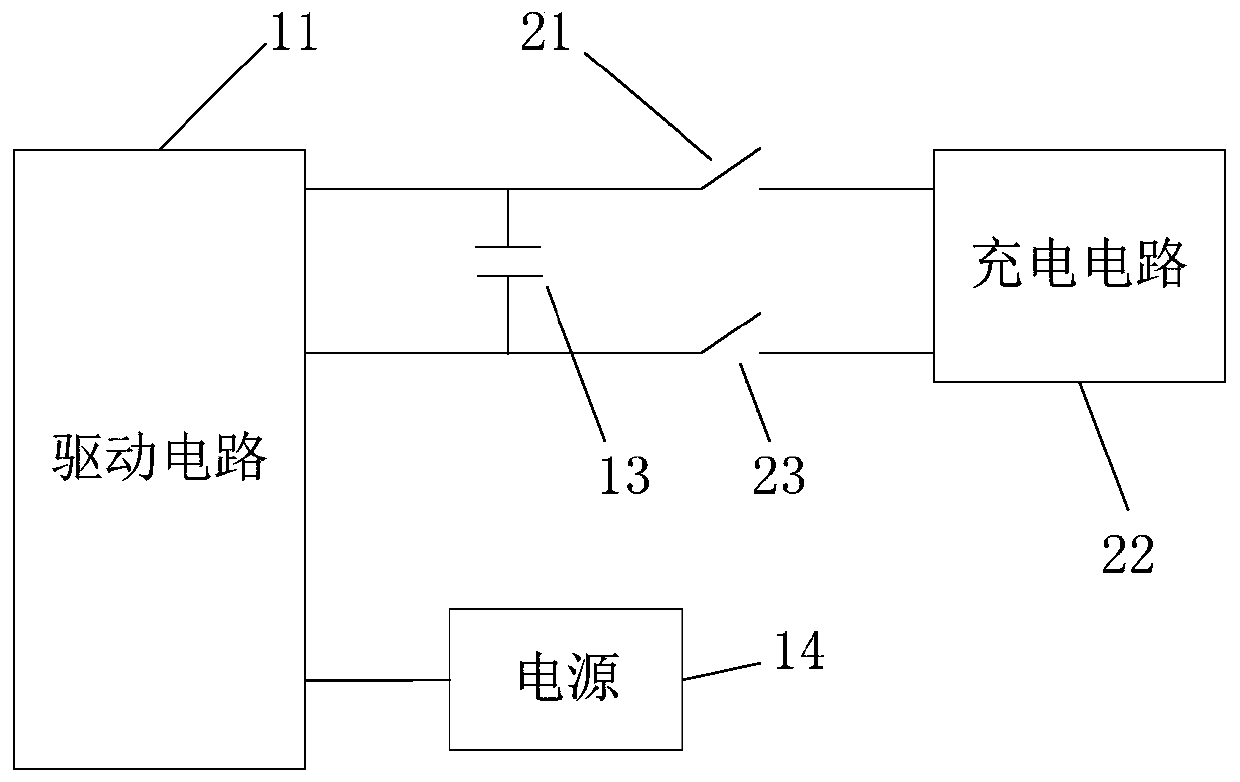
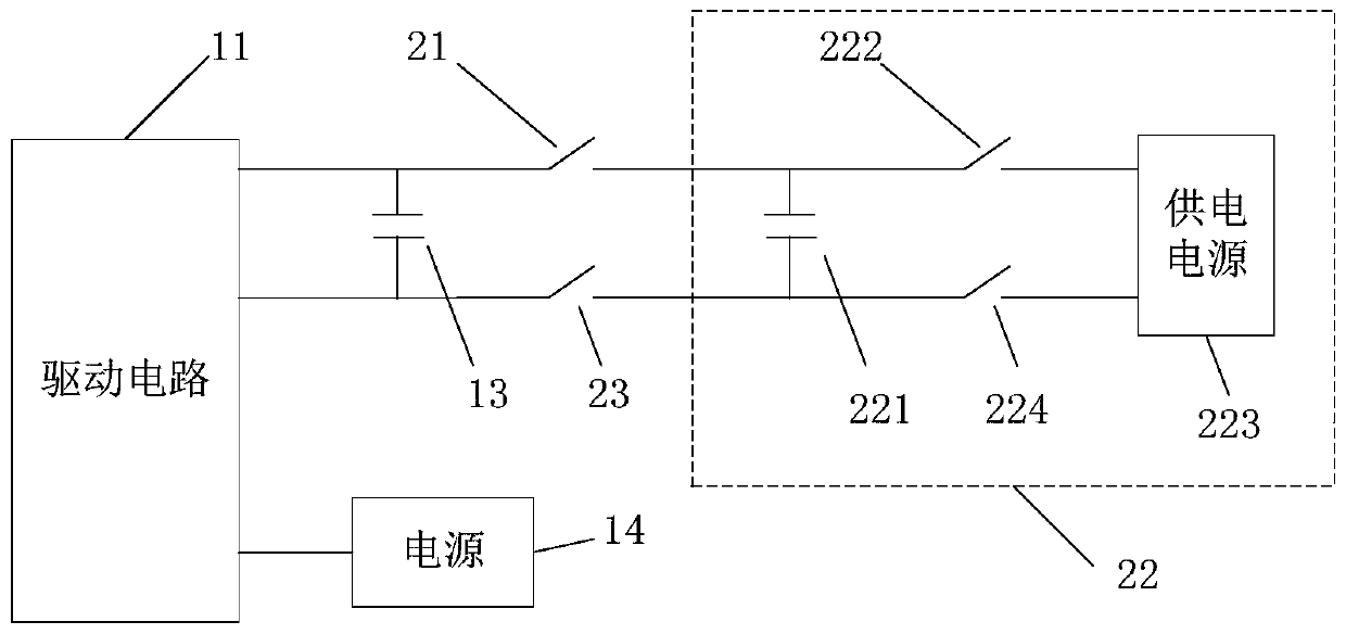
The invention provides a switching power supply capacitor charging circuit and a charging method. The switching power supply capacitor charging circuit comprises a first capacitor, a first switch, a second switch and a charging circuit, wherein the first capacitor is suitable for being connected to the power supply end of a switching power supply driving circuit to provide pumping voltage for thedriving circuit; the first end of the first switch is connected to the first end of the first capacitor, and the second end is connected to the output end of the charging circuit; the first end of thesecond switch is connected to the second end of the first capacitor and the second end is connected to the grounding end of the charging circuit; and the charging circuit is configured to charge thefirst capacitor when the first switch and the second switch are closed. Thus, the problems that the existing switching power supply pumping capacitor charging circuit can not charge the pumping capacitor before the switching power supply control circuit is started, and the driving efficiency is low can be solved.

Description

technical field [0001] The invention relates to the technical field of switching power supplies, in particular to a switching power supply capacitor charging circuit and a charging method. Background technique [0002] The input terminal of the drive circuit 11 of the existing switching power supply is connected with a power supply 14, but if the output terminal of the drive circuit 11 is connected with a half-bridge MOS tube, and when the upper tube MOS tube of the half-bridge MOS tube is an N-channel MOS tube, due to the power supply The voltage is small, and the driving circuit 11 cannot normally drive the control circuit connected to the output terminal, so, as figure 1 As shown, the input end of the driving circuit 11 is usually connected with a first capacitor 13, which is usually called a pumping capacitor. In the prior art, after the power supply 14 normally supplies power to the driving circuit 11, the circuit inside the driving circuit 11 charges the pumping capac...

Claims


Application Information

Patent Timeline
IPC IPC(8): H02M1/36H02J7/34
Inventor 康振华于江涛
Owner GUANGZHOU XAIRCRAFT TECH CO LTD
Learn More