An antenna adjusting method and an antenna system terminal

A technology of antenna system and adjustment method, which is applied in the direction of radio transmission system, antenna, transmission system, etc., and can solve the problems of accuracy decline, GPS sensitivity attenuation, high sensitivity, etc.

Inactive Publication Date: 2019-06-07
HUIZHOU TCL MOBILE COMM CO LTD
View PDF6 Cites 6 Cited by
  • Summary
  • Abstract
  • Description
  • Claims
  • Application Information

AI Technical Summary

Problems solved by technology

[0003] In the prior art, GPS (Global Positioning System, Global Positioning System) is applied to user mobile phones and other mobile terminals, and mobile phone GPS navigation has also become the mainstream of self-driving navigation, personal travel, etc.; but the sensitivity of GPS is relatively high. There are similar interference signals in the band, which will interfere with the performance of GPS, resulting in a decrease in accuracy; therefore, the positioning accuracy of mobile phone GPS technology will directly affect the user experience
[0004] AGPS (Assisted Global Positioning System, Assisted Global Positioning System) is an operation mode of GPS. It mainly uses the signal resources of mobile phone base stations and cooperates with traditional GPS satellite positioning technology to make GPS positioning faster; however, AGPS positioning The technology is mainly through the communication of the main radio frequency of the mobile terminal, which will involve the passage of LTE B13 / 14, and the second harmonic of the B13 / 14 will fall within the GPS frequency, causing interference to GPS performance, resulting in attenuation of GPS sensitivity, making Inaccurate or even impossible to locate

Method used

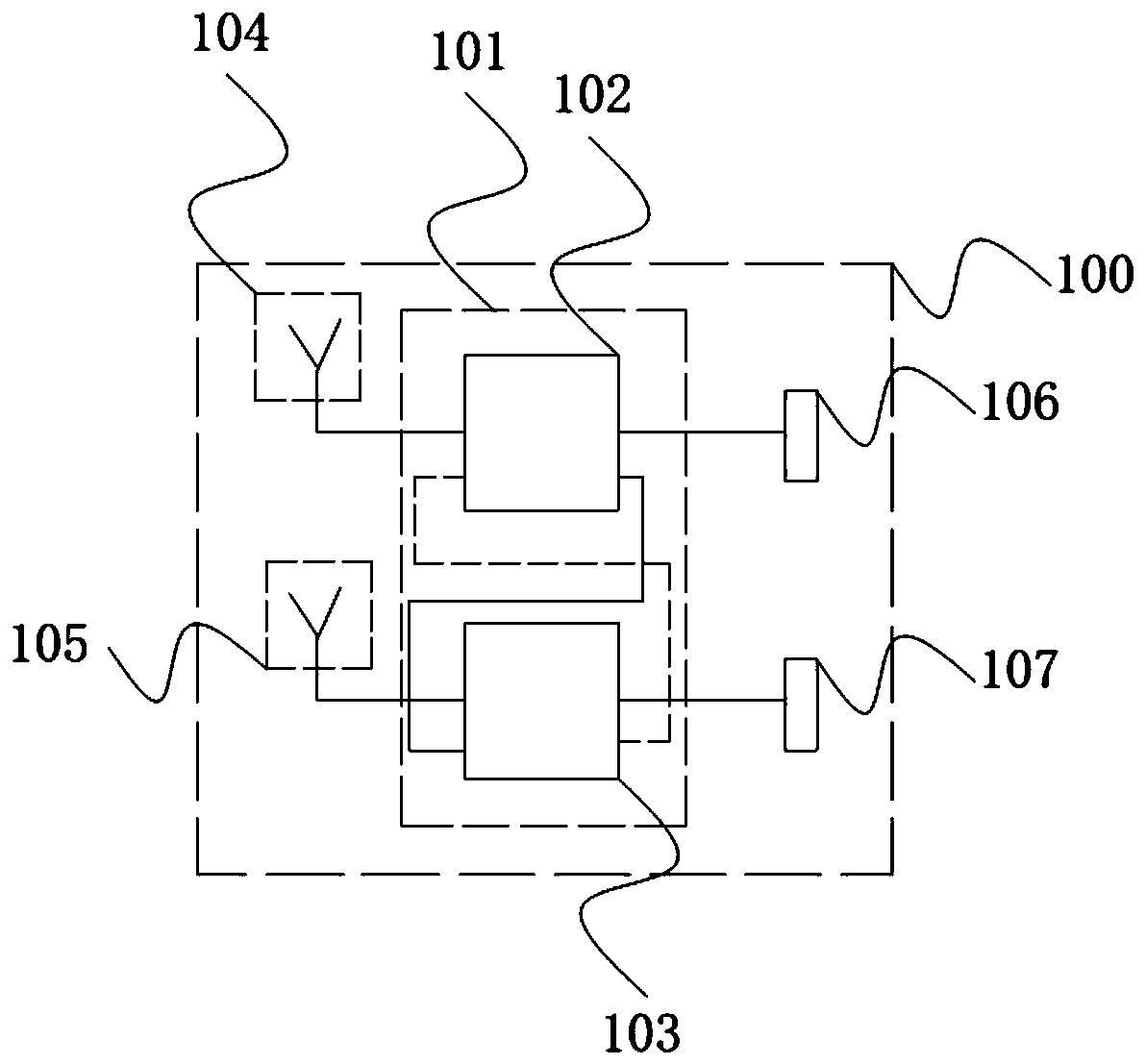
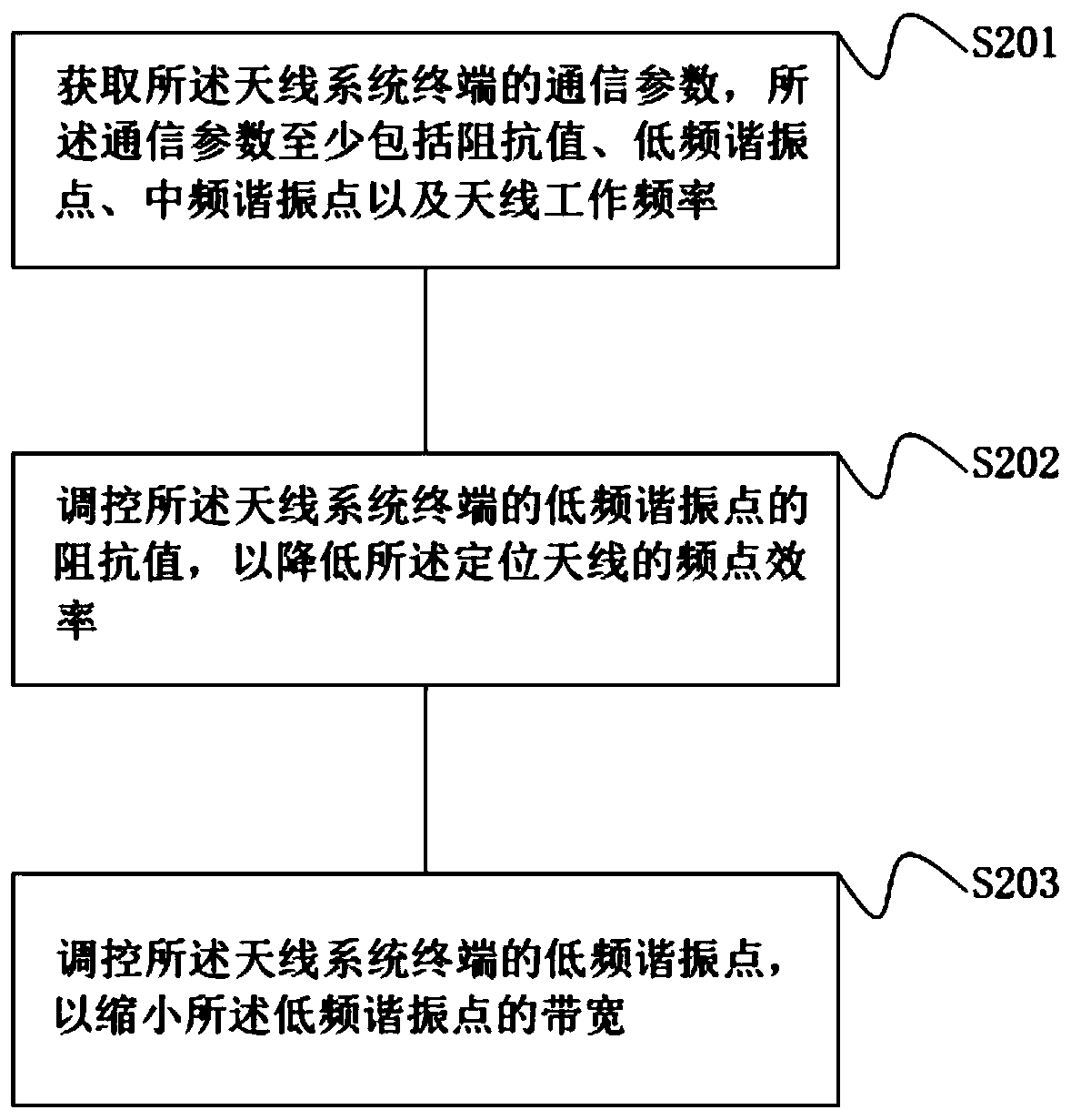
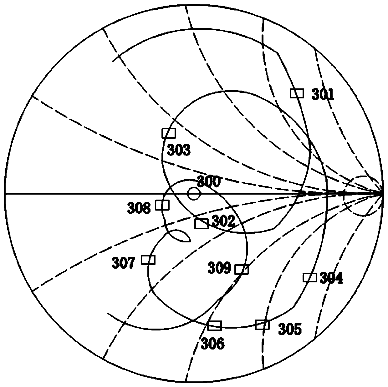

Image

  • An antenna adjusting method and an antenna system terminal
  • An antenna adjusting method and an antenna system terminal
  • An antenna adjusting method and an antenna system terminal

Examples


Embodiment Construction

[0030] The following descriptions of the various embodiments refer to the attached drawings to illustrate specific embodiments that the present application can be implemented in. The directional terms mentioned in this application, such as "up", "down", "front", "rear", "left", "right", "inside", "outside", "side", etc., are for reference only The orientation of the attached schema. Therefore, the directional terms used are used to illustrate and understand the application, but not to limit the application.

[0031] The drawings and descriptions are to be regarded as illustrative in nature and not restrictive. In the figures, structurally similar units are denoted by the same reference numerals. In addition, the size and thickness of each component shown in the drawings are arbitrarily shown for understanding and convenience of description, but the present application is not limited thereto.

[0032] In the drawings, the thickness of layers, films, panels, regions, etc., ar...


PUM


Abstract

The invention provides an antenna adjusting method and an antenna system terminal, the antenna adjusting method is applied to the antenna system terminal, and the antenna system terminal comprises a diversity antenna and a positioning antenna; The antenna adjusting method comprises the steps of obtaining communication parameters of the antenna system terminal, wherein the communication parametersat least comprise an impedance value, a low-frequency resonance point and an intermediate-frequency resonance point; Regulating and controlling a low-frequency resonance point of the antenna system terminal so as to reduce the bandwidth of the low-frequency resonance point; Adjusting and controlling an impedance value of a low-frequency resonance point of the antenna system terminal so as to reduce the frequency point efficiency of the positioning antenna; Wherein by controlling the impedance value of the antenna system terminal, the bandwidth of the low-frequency resonance point is regulatedand controlled, and the second harmonic energy generated by a communication channel is reduced; Through the antenna control method, the interference of second harmonic energy on the positioning systemcan be reduced, the sensitivity of the positioning system is improved, and the accuracy of the positioning system is improved.

Description

technical field [0001] The present invention relates to the technical field of antenna control methods, in particular, to an antenna adjustment method and an antenna system terminal. Background technique [0002] GPS (Global Positioning System, Global Positioning System) not only played a huge role in the early military field, but also in the field of real technology, GPS technology has been widely used in traffic navigation, terrain investigation, surveying and mapping, etc. [0003] In the prior art, GPS (Global Positioning System, Global Positioning System) is applied to user mobile phones and other mobile terminals, and mobile phone GPS navigation has also become the mainstream of self-driving navigation, personal travel, etc.; but the sensitivity of GPS is relatively high. Similar interference signals in the band will interfere with the performance of GPS, resulting in a decrease in accuracy; therefore, the positioning accuracy of mobile phone GPS technology will direct...

Claims


Application Information

Patent Timeline
Patent Type & Authority Applications(China)
IPC IPC(8): H04B1/00H04B1/40H04B7/0404H04W4/024H01Q1/50H01Q23/00
Inventor 张生张华
Owner HUIZHOU TCL MOBILE COMM CO LTD
Why Eureka
Try Eureka