A method for manufacturing an MEMS microphone support plate with porous sound inlet and single-hole sound transmission

A manufacturing method and microphone technology, which are applied to electrostatic transducer microphones, sensors, electrical components, etc., can solve the problems of increasing the overall thickness of the finished MEMS microphone, limiting the lifting space of the MEMS microphone, and the limited cavity space of the size of the steel sheet opening. Achieve the effect of improving microphone performance, simplifying the chip placement process, and improving the effect significantly

Active Publication Date: 2019-06-07
JIANGSU PROVISION ELECTRONICS CO LTD
View PDF11 Cites 5 Cited by
  • Summary
  • Abstract
  • Description
  • Claims
  • Application Information

AI Technical Summary

Problems solved by technology

[0002] The finished MEMS microphone carrier board is a conventional single-hole sound-input and single-hole sound-transmission design. If it is necessary to realize the change of part of the sound cavity space in the sound transmission path, it is necessary to add a steel sheet with holes between the sound transmission sound hole and the chip, so it will increase the number of finished MEMS. The overall thickness of the microphone is also limited by the size of the sound transmission port of the chip. The size of the opening of the steel sheet and the space formed by the cavity are limited, and the sound inlet sound hole cannot be too large to affect the dustproof effect. Therefore, this method limits the transmission of the MEMS microphone. Room for improvement in sound performance

Method used


Image

  • A method for manufacturing an MEMS microphone support plate with porous sound inlet and single-hole sound transmission
  • A method for manufacturing an MEMS microphone support plate with porous sound inlet and single-hole sound transmission
  • A method for manufacturing an MEMS microphone support plate with porous sound inlet and single-hole sound transmission

Examples


Embodiment Construction

[0034] Hereinafter, a preferred embodiment of the present invention will be described in detail with reference to the accompanying drawings. However, the scope of protection of the present invention is not limited to the following embodiments, that is, all simple equivalent changes and modifications made based on the scope of the patent application of the present invention and the content of the specification are still within the scope of the patent of the present invention.

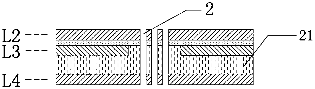
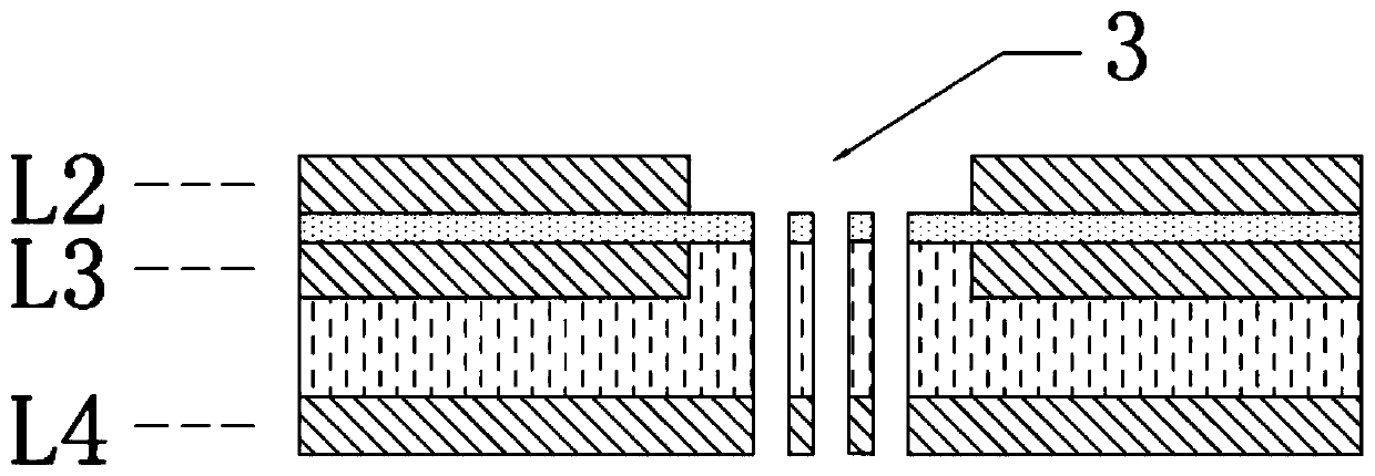
[0035] Refer to Figure 1-6 , Is a method for manufacturing a porous sound-inlet single-hole sound transmission MEMS microphone carrier board of the present invention, including the following steps:

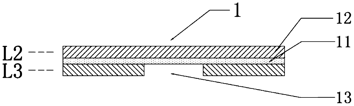
[0036] Step 1. Prepare an embedded capacitor substrate 1. The embedded capacitor substrate includes a capacitor layer 11 and a conductive copper foil layer 12 located on both sides of the capacitor layer 11. The two conductive copper foil layers form a second circuit layer L2 and a third circuit layer L2, respec...


PUM


Abstract

The invention discloses a method for manufacturing an MEMS microphone support plate with porous sound inlet and single-hole sound transmission, and the method can omit a traditional microphone mounting process for realizing the cavity expansion of a sound transmission path through the chip mounting through a hole steel sheet through the design of embedding a sound cavity in the support plate, thereby simplifying the chip mounting process, and reducing the cost investment. Through the design of embedding the sound cavity in the support plate, the sound transmission sound cavity with high variability is formed in the sound path of the microphone, which is conducive to improving the frequency response and improving the performance of the microphone. Through the miniature porous design of thesound inlet sound hole, the sound inlet volume can be ensured, the dustproof effect is achieved, the butt joint with the chip through the single sound transmission hole in the embedded sound cavity isachieved, and the sound transmission performance of the microphone can be greatly improved; And the single-process production process is mature, the production cost investment is low, the improvementeffect is remarkable, and the performance of terminal products is improved.

Description

Technical field [0001] The invention relates to a manufacturing method of a MEMS microphone carrier board, in particular to a manufacturing method of a MEMS microphone carrier board with porous sound-inlet single-hole sound transmission. Background technique [0002] The finished MEMS microphone carrier board is a conventional single-hole sound-into-single-hole sound transmission design. If a part of the acoustic cavity space in the sound transmission path needs to be changed, a steel sheet with a hole must be added between the sound transmission sound hole and the chip, so the finished MEMS will be added. The overall thickness of the microphone is also limited by the size of the sound port of the chip. The size of the opening of the steel sheet and the space of the cavity formed are limited, and the sound inlet hole cannot be too large, which will affect the dustproof effect. Therefore, this method limits the transmission of the MEMS microphone. Room for improvement of sound per...

Claims


Application Information

Patent Timeline
Patent Type & Authority Applications(China)
IPC IPC(8): H04R31/00H04R19/04
Inventor 马洪伟陆敏晨
Owner JIANGSU PROVISION ELECTRONICS CO LTD
Why Eureka
Try Eureka