Slider controlled cooking appliances

A technology of cooking utensils and sliders, which is applied in the field of cooking utensils controlled by sliders, and can solve problems such as inability to realize productization, affecting the service life of the scroll wheel sliding tuning keys, obstacles, etc.

Active Publication Date: 2021-07-06
JOYOUNG CO LTD
View PDF4 Cites 0 Cited by
  • Summary
  • Abstract
  • Description
  • Claims
  • Application Information

AI Technical Summary

Problems solved by technology

However, the environment used by cooking utensils is more complicated and harsh than the environment used by mice or mixers. In the environment used by cooking utensils, the problem of water ingress and the complexity of the force seriously affect the scroll wheel or the sliding tuning key. The service life of the application has serious obstacles, and it is impossible to achieve normal productization

Method used


Image

  • Slider controlled cooking appliances
  • Slider controlled cooking appliances
  • Slider controlled cooking appliances

Examples


Embodiment 1

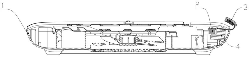
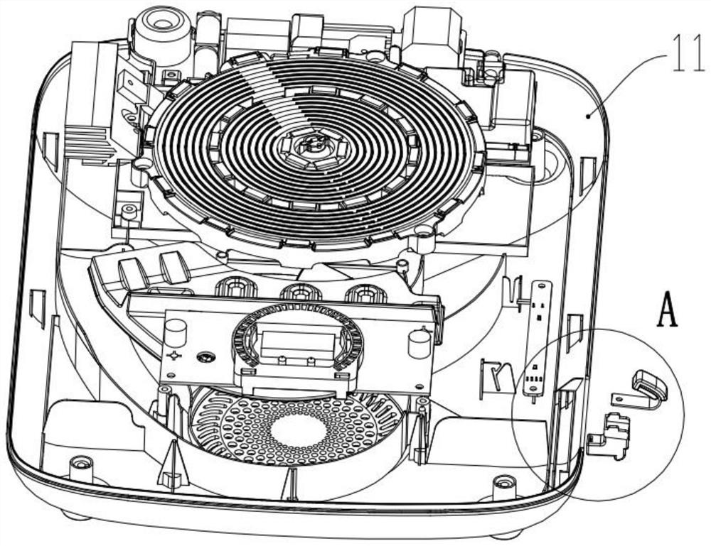
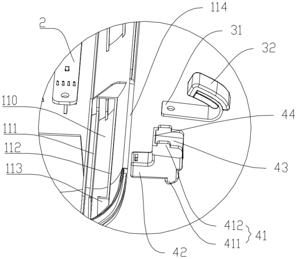
[0038] See Figure 1 to Figure 6, which is a diagram of a cooking appliance controlled by a slider in Embodiment 1 of the present invention. In this embodiment, the cooking utensil is an induction cooker, which includes a housing 1, a slide bar assembly 2 installed in the housing 1, a sliding bar 3 exposed outside the housing 1, and a sliding bar assembly connected to the sliding bar. 3 and the connecting seat 4 between the slider assembly 2. The slide bar 3 is arranged on the right side of the induction cooker and close to the front end of the induction cooker, which conforms to human body mechanics and is convenient for toggle operation. The housing 1 is provided with chute 110, 120, and the connecting seat 4 is provided with sliders 411, 412, and the sliders 411, 412 can slide in the chute 110, 120, so that the connecting seat 4 Slidingly connected with the sliding bar assembly 2 , the sliding bar 3 is fixed on the connecting seat 4 so as to be slidably connected with the...

Embodiment 2

[0047] see Figure 7 , which is a diagram of the connecting seat of the second embodiment of the present invention, which is different from the first embodiment in that the sliding block is also provided with a sliding slot. Specifically, the connecting base 4 includes a lower slider and an upper slider 412, the upper slider 412 is also provided with a sliding slot 4120, and the corresponding sliding slot 120 on the upper cover 12 is also provided with a sliding slot along the length of the sliding slot. The sliding guide plate (not shown) extending in the direction, the sliding slot 4120 is inserted on the upper end of the sliding guide plate, and the sliding guide plate cooperates with the sliding slot 4120 to further guide the sliding. In order to ensure smooth sliding, the connecting seat 4 is preferably made of POM (polyoxymethylene resin) plastic, because POM plastic itself has better lubricating properties, which can enhance smooth sliding; lubricant can also be applied...


PUM


Abstract

The invention discloses a cooking appliance controlled by a slider, which includes a housing, a slider assembly installed in the housing, and a slider exposed outside the housing. The cooking appliance also includes a The connecting seat on the body, one of the housing and the connecting seat is provided with a slide groove, and the other is provided with a slider slidingly fitted with the slide groove, and the connecting seat is slidably connected with the slider assembly , the sliding bar is fixed on the connecting seat, so as to be slidably connected with the sliding bar assembly through the connecting seat. The present invention is provided with a connecting seat, which is used for guiding sliding, bearing force and waterproofing, which can effectively prevent the slider assembly from being damaged by force or water ingress, and improve the service life.

Description

technical field [0001] The invention relates to the field of kitchen appliances, in particular to a cooking appliance controlled by a slide bar. Background technique [0002] At present, most kitchen cooking appliances have multiple functions and multiple adjustable heating powers for users to choose according to cooking types. Taking an induction cooker as an example, it usually has cooking functions, hot pot functions, timing functions, and constant temperature functions; and the power has such as 300W, 600W, 900W, 1200W, 1500W, 1800W, 2000W, 2200W, etc. When the user needs to stir-fry, he will select the stir-frying function, and at the same time, it will adjust to a high power such as 2000W during the stir-frying stage, and it will adjust to a low power such as 600W during the stewing stage. It can be seen that the user will make multiple adjustments when cooking. In the prior art, there are usually two ways to adjust the power. One is to adjust the power through the a...

Claims


Application Information

Patent Timeline
Patent Type & Authority Patents(China)
IPC IPC(8): A47J27/00A47J36/00
Inventor 朱泽春马文金立旺
Owner JOYOUNG CO LTD
Why Eureka
Try Eureka