
Keyboard equipment and a touchpad device thereof

A touch panel and equipment technology, applied in the fields of instruments, computing, electrical and digital data processing, etc., can solve problems such as the inability to effectively reduce the overall height of the keys, increase the manufacturing cost and assembly time of the keyboard, and disadvantage the thin design of the keys, etc.

Active Publication Date: 2019-06-11
DARFON ELECTRONICS (SUZHOU) CO LTD +1
View PDF10 Cites 2 Cited by
  • Summary
  • Abstract
  • Description
  • Claims
  • Application Information

AI Technical Summary

Problems solved by technology

In the prior art, in order to configure the touchpad device on one side of the keyboard keys, the common design would be to add an engaging frame structure on the key support iron plate to be used for the button piece of the touchpad device. However, this design that requires an additional welded frame structure on the supporting iron plate will not only increase the manufacturing cost and assembly time of the keyboard, but also cannot effectively reduce the overall height of the keys, which is not conducive to the thinness of the keys. design

Method used


Image

  • Keyboard equipment and a touchpad device thereof
  • Keyboard equipment and a touchpad device thereof
  • Keyboard equipment and a touchpad device thereof

Examples


Embodiment Construction

[0031] The aforementioned and other technical contents, features and effects of the present invention will be clearly presented in the following detailed description of a preferred embodiment with reference to the drawings. The directional terms mentioned in the following embodiments, such as: up, down, left, right, front or back, etc., are only directions referring to the attached drawings. Accordingly, the directional terms are used to illustrate and not to limit the invention.

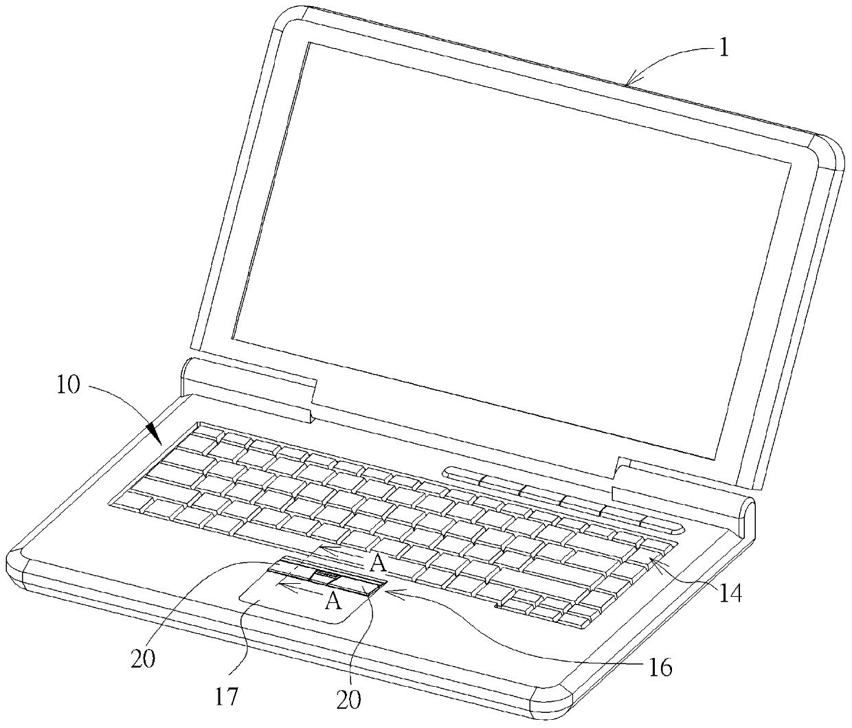
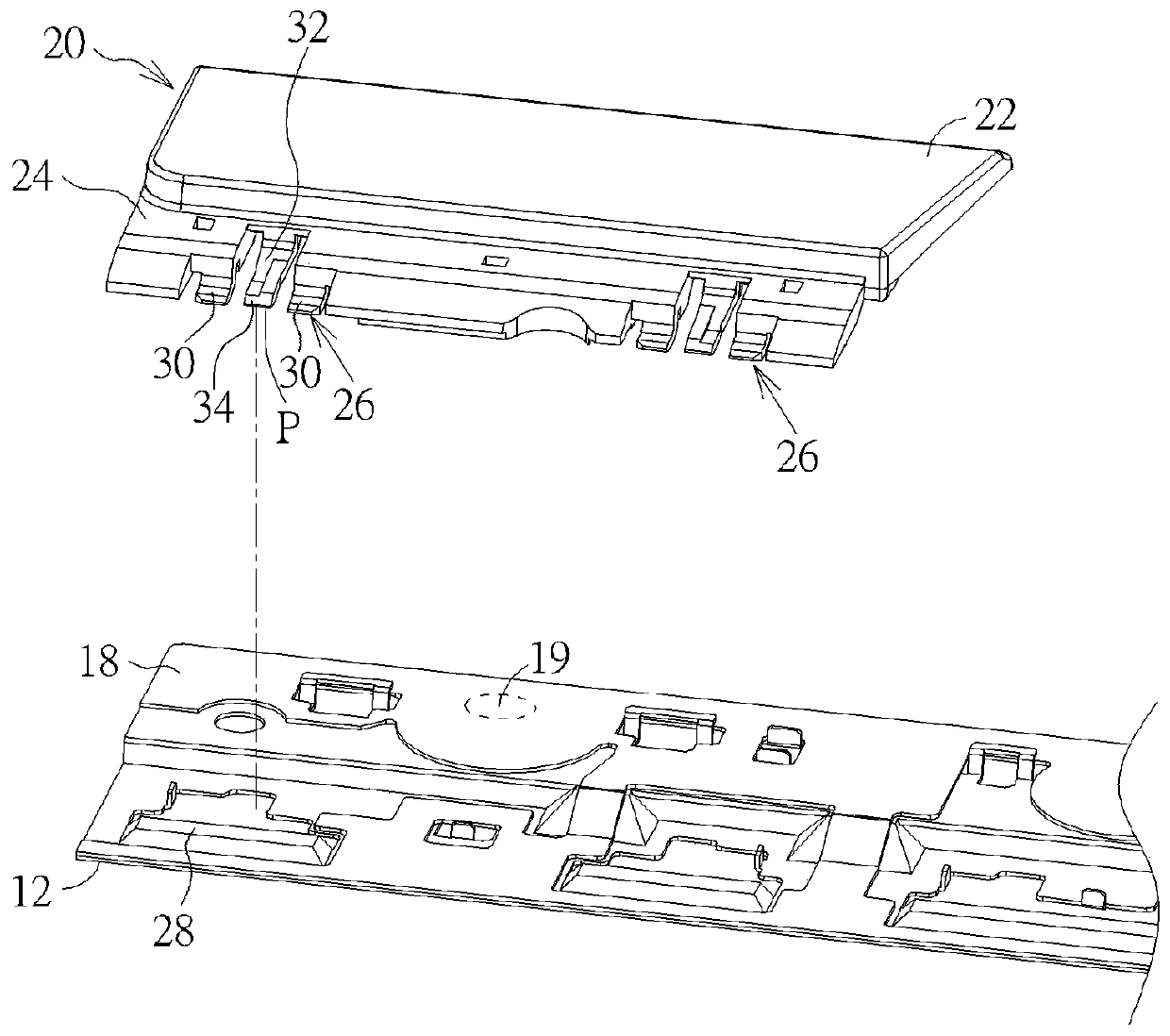
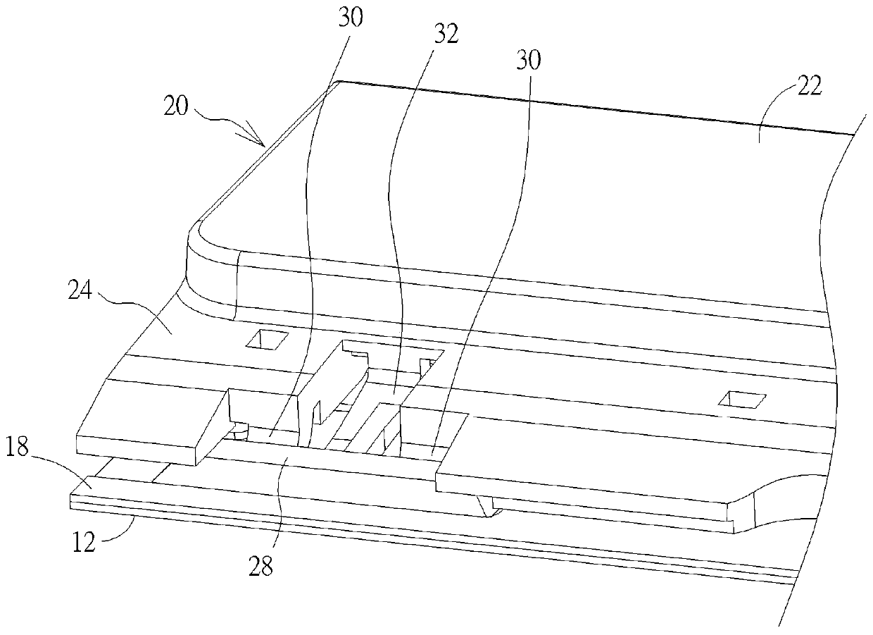
[0032] see figure 1 , figure 2 as well as image 3 , figure 1 It is a three-dimensional schematic diagram of a keyboard device 10 proposed according to an embodiment of the present invention, figure 2 for figure 1 Partial explosion schematic diagram of midsole plate 12, button piece 20 and circuit board 18, image 3 for figure 2 The schematic diagram of the assembly of the middle bottom plate 12, the button piece 20 and the circuit board 18, as figure 1 , figure 2 as well as image 3 A...


PUM


Abstract

The invention relates to keyboard equipment and a touchpad device thereof. The keyboard equipment comprises a bottom plate, a plurality of keys, the touchpad device and a circuit board, The pluralityof keys are arranged on the bottom plate. The touchpad device comprises a touchpad and a button piece. The touchpad is arranged on the bottom plate and located on one side of the keys. The button piece is located between the button and the touchpad and is provided with a pressing piece part and an elastic arm part. wherein the elastic arm part extends towards the key from the pressing sheet part and forms a three-jaw clamping structure, a protruding clamping structure is formed at the position, corresponding to the three-jaw clamping structure, of the bottom plate, and the three-jaw clamping structure is clamped to the protruding clamping structure in a pivotable mode, so that the pressing sheet part can move up and down relative to the bottom plate. According to the button piece, the three-jaw clamping structure of the elastic arm part is directly utilized to extend into and be clamped in the protruding clamping structure to be pivoted to the bottom plate, a clamping frame structure does not need to be additionally formed on the bottom plate through hot melting, the manufacturing cost and the assembling time of the keyboard can be reduced, and the overall height of the key can bereduced.

Description

technical field [0001] The present invention relates to a keyboard device and a touch panel device thereof, in particular to a keyboard device and a touch panel device thereof in which a button piece of a touch panel is pivotally engaged on a bottom plate by using a three-claw engaging structure. Background technique [0002] As far as current personal computer usage habits are concerned, the keyboard is one of the indispensable input devices for inputting characters, symbols or numbers. With the gradual popularization of computers, the development of buttons and keyboards now emphasizes the integration design with other input devices in addition to general input functions. Representative design. In the prior art, in order to configure the touchpad device on one side of the keyboard keys, the common design would be to add an engaging frame structure on the key support iron plate to be used for the button piece of the touchpad device. However, this design that requires an a...

Claims


Application Information

Patent Timeline
Patent Type & Authority Applications(China)
IPC IPC(8): G06F3/02G06F3/041
Inventor 蔡柏伟王俊元
Owner DARFON ELECTRONICS (SUZHOU) CO LTD
Learn More