Lifting platform used for tile cutting machine and tile cutting machine

A lifting platform and cutting machine technology, applied in the direction of working accessories, manufacturing tools, stone processing equipment, etc., can solve the problems of cutting blade breakage, troublesome operation, limited use occasions, etc., to improve processing accuracy and efficiency, and improve the lifting/lowering process Smooth, wide-ranging effects

Pending Publication Date: 2019-06-14
四川省万光机械设备有限公司
View PDF8 Cites 2 Cited by
  • Summary
  • Abstract
  • Description
  • Claims
  • Application Information

AI Technical Summary

Problems solved by technology

[0003] However, the cutting machines commonly used in the prior art, especially portable small cutting machines, usually have some disadvantages in actual use. The surface of the stone is molded in various shapes, such as processing grooves with different depths (that is, slotting), etc., and the existing cutting machine, either cannot adjust the height of the cutting blade in the vertical direction (that is, it is impossible to adjust the height of the cutting blade and the cutting blade). The distance between the worktables) can only be used to cut through tiles or stones, but not on the surface of tiles or stones. Not only is the use occasion limited, but also when cutting thicker tiles or stones, it is easy to cause the cutting piece to break ; or the height of the cutting piece can only be adjusted by adjusting the installation height of the guide rail. The depth of the grooves is different, which affects the appearance

Method used


Image

  • Lifting platform used for tile cutting machine and tile cutting machine
  • Lifting platform used for tile cutting machine and tile cutting machine
  • Lifting platform used for tile cutting machine and tile cutting machine

Examples


Embodiment 1

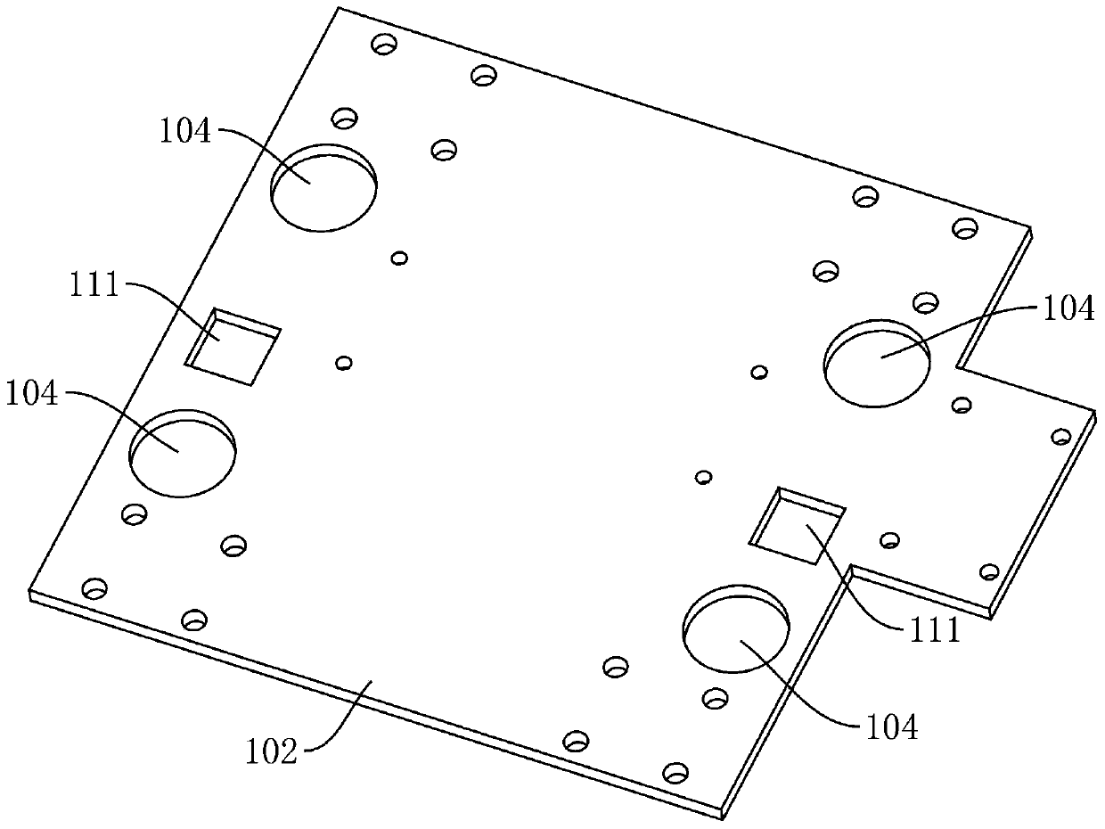
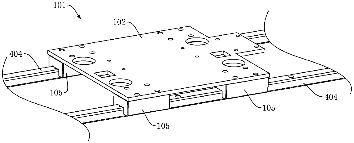
[0045] see figure 2 , Figure 5 , Figure 6 , Figure 7 and Figure 8In this embodiment, a lifting platform for a tile cutter is provided, including a movable part 201 and a fixed part 101, wherein the movable part 201 is used for installing a motor 401 and a cutting piece 403, and the fixed part 101 is used for installing on a guide rail 404, and can move along the length direction of the guide rail 404, the movable part 201 is connected with the fixed part 101, and forms a mobile pair with the fixed part 101 that can move up / down in the vertical direction, that is, the movable part 201 can be relatively fixed The part 101 moves up / down, and synchronously drives the motor 401 and the cutting piece 403 on it to move up / down, so as to effectively adjust the distance between the cutting piece 403 and the ceramic tile or stone below, so that the ceramic tile and stone can be easily cut. Various shapes of the surface, especially grooves with different processing depths, compa...

Embodiment 2

[0060] This embodiment provides a tile cutting machine, including a guide rail 404, a motor 401, a transmission shaft 402, a second transmission mechanism 405 and the aforementioned lifting platform, such as Figure 10 As shown, the fixed part 101 is fixed on the guide rail 404 and can slide along the length direction of the guide rail 404, the motor 401 is fixed on the movable part 201, and the output shaft of the motor 401 communicates with the second transmission mechanism 405 through the second transmission mechanism 405. The transmission shaft 402 is connected, the transmission shaft 402 is fixed on the movable part 201, the transmission shaft 402 is used to install the cutting piece 403, the second transmission mechanism 405 can be a belt transmission mechanism or a gear 304 transmission mechanism or a chain transmission mechanism, etc. The motor 401 drives the cutting piece 403 to rotate through the second transmission mechanism 405, thereby realizing the cutting functio...


PUM


Abstract

The invention relates to a lifting platform used for a tile cutting machine and the the tile cutting machine. The lifting platform comprises a movable part and a fixed part. The movable part is used for installing a motor and a cutting blade. The fixed part is used for being installed on a guide rail. The movable part is connected with the fixed part and forms a movable pair with the fixed part, wherein the movable pair can move upwards or downwards in the vertically direction. The lifting platform is compact in structure, the height of the cutting blade can be adjusted conveniently, rapidly and efficiently in the tile machining process, the grooving and cutting depth can be accurately controlled, fine adjustment is conducted after cutting blade abrasion, in addition, operation in the adjusting process can be better simplified, and the machining precision and efficiency are improved.

Description

technical field [0001] The invention relates to the technical field of cutting tools, in particular to a lifting platform for a tile cutting machine and the tile cutting machine. Background technique [0002] Cutting machine is a common tool for cutting boards such as tiles; cutting machine in the prior art usually includes workbench, guide rail support, sliding platform, motor and cutting sheet, etc., workbench is used to place or arrange the tiles to be cut, guide The bracket usually includes a guide rail and two support plates, the two ends of the guide rail are respectively fixed on the support plate, the support plates are respectively fixed on the workbench, the sliding platform is arranged on the guide rail, the motor and the cutting blade are respectively fixed on the sliding platform, and the output shaft of the motor The transmission mechanism is connected with the cutting piece so as to drive the cutting piece to rotate, and the sliding platform can slide along th...

Claims


Application Information

Patent Timeline
Patent Type & Authority Applications(China)
IPC IPC(8): B28D1/24B28D7/00B28D7/04
Inventor 江斐杨海林
Owner 四川省万光机械设备有限公司
Why Eureka
Try Eureka