A vehicle automatic forced deceleration and speed limiting system and method

A braking deceleration and vehicle technology, applied in control/regulation systems, vehicle accessories, vehicle parts, etc., can solve problems such as inapplicability and failure to consider collisions, so as to improve driving safety and reduce road congestion and traffic accidents Effect

Active Publication Date: 2019-06-14
JIANGSU UNIV
View PDF9 Cites 7 Cited by
  • Summary
  • Abstract
  • Description
  • Claims
  • Application Information

AI Technical Summary

Problems solved by technology

Existing speed limit methods mostly remind drivers to take correct driving behavior by placing speed limit signs and construction signs. Conflicts are likely to occur in the work area, resulting in serious traffic accidents
Chinese patent (CN108297868A) discloses a vehicle automatic mandatory speed limit cruising system on a speed limit road section. The system includes a speed limit signal transmitter, a vehicle signal receiver, an adaptive cruise controller, a vehicle CAN bus, and an actuator. After the signal receiver receives the signal, it transmits an instruction to force the vehicle to automatically cruise. This invention is limited to fixed speed limit roads such as campuses and residential areas, and does not consider whether the vehicle will collide with the vehicle in front or behind after the mandatory speed limit is imposed. , so that the system itself has limitations and cannot be applied to situations where there are many vehicles in the expressway maintenance area and the speed is fast

Method used


Image

  • A vehicle automatic forced deceleration and speed limiting system and method
  • A vehicle automatic forced deceleration and speed limiting system and method
  • A vehicle automatic forced deceleration and speed limiting system and method

Examples


Embodiment Construction

[0023] The present invention will be described in further detail below through specific embodiments, but the protection scope of the present invention is not limited thereto.

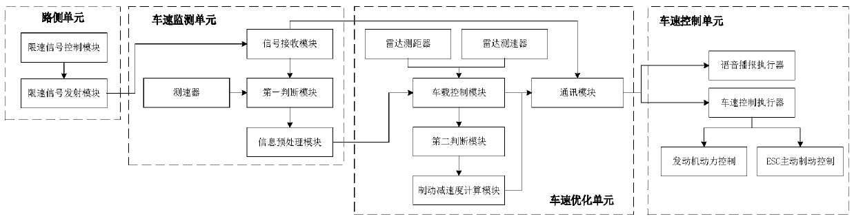
[0024] Such as figure 1 As shown, the present invention relates to a vehicle automatic forced deceleration and speed limit system for avoiding traffic conflicts in expressway maintenance work areas, including four parts: a roadside unit, a vehicle speed monitoring unit, a vehicle speed optimization unit, and a vehicle speed control unit; the roadside unit is set In the expressway maintenance work area, the vehicle speed monitoring unit, the vehicle speed optimization unit and the vehicle speed control unit are set on the vehicle.

[0025] The roadside unit includes a speed limit signal control module and a speed limit signal transmission module. The speed limit signal control module is used to store the real-time control information of the speed limit signal. The real-time control information of the spe...


PUM


Abstract

The invention relates to a vehicle automatic forced deceleration and speed limiting system that comprises a road side unit, a vehicle speed monitoring unit, a vehicle speed optimization unit, and a vehicle speed control unit; the road side unit comprises a speed limiting signal control and transmitting module; the vehicle speed monitoring unit comprises a signal receiving module, a velometer, a first judgment module and an information preprocessing module; the vehicle speed optimization unit comprises a radar range finder, a radar velometer, a vehicle-mounted control module, a second judgmentmodule, a brake deceleration calculation module and a communication module; the vehicle speed control unit comprises a voice broadcast actuator, a vehicle speed control actuator, an engine power control and an ESC active brake control. The invention further relates to a vehicle automatic forced deceleration and speed limiting method; starting from the vehicle distance and the vehicle speed, the range of braking deceleration adopted by the vehicle in order to avoid conflicts with front and rear vehicles is accurately calculated, the driving safety is improved when the vehicle is subjected to speed control, and the accident risk caused by vehicle overspeed passing in expressway maintenance operation areas is greatly reduced.

Description

technical field [0001] The present invention relates to the fields of automatic vehicle control and traffic safety, and in particular to a roadside unit set facing the expressway maintenance work area. A method of safely and automatically decelerating and speed limiting within the vehicle. Background technique [0002] With the continuous and rapid development of my country's economy and society, the traffic volume of expressways has increased rapidly, and the expressways built in the early days of our country have entered the stage of daily maintenance, major and medium repairs or reconstruction and expansion. Some lanes need to be closed during expressway maintenance work, and vehicles need to perform actions such as early deceleration and forced merging in advance to ensure safe passage through the construction area. Existing speed limit methods mostly remind drivers to take correct driving behavior by placing speed limit signs and construction signs. Conflicts are like...

Claims


Application Information

Patent Timeline
Patent Type & Authority Applications(China)
IPC IPC(8): B60W30/14B60W50/14B60K31/00
Inventor 葛慧敏夏然杨友森孙辉黄明月
Owner JIANGSU UNIV
Why Eureka
Try Eureka