Continuous-intermittent rotary lifting work arm mechanism and application method
A working arm and space technology, which is applied in the field of continuous intermittent rotary lifting working arm mechanism, can solve the problems of slow rotary jacking speed, complicated operation and high cost, and achieve the effect of ensuring stability, speed, and flexibility.
- Summary
- Abstract
- Description
- Claims
- Application Information
AI Technical Summary
Problems solved by technology
Method used
Image
Examples
Embodiment 1
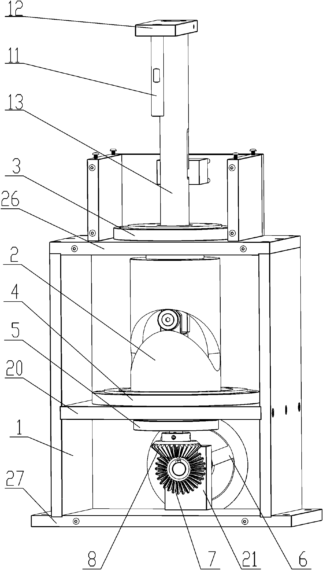
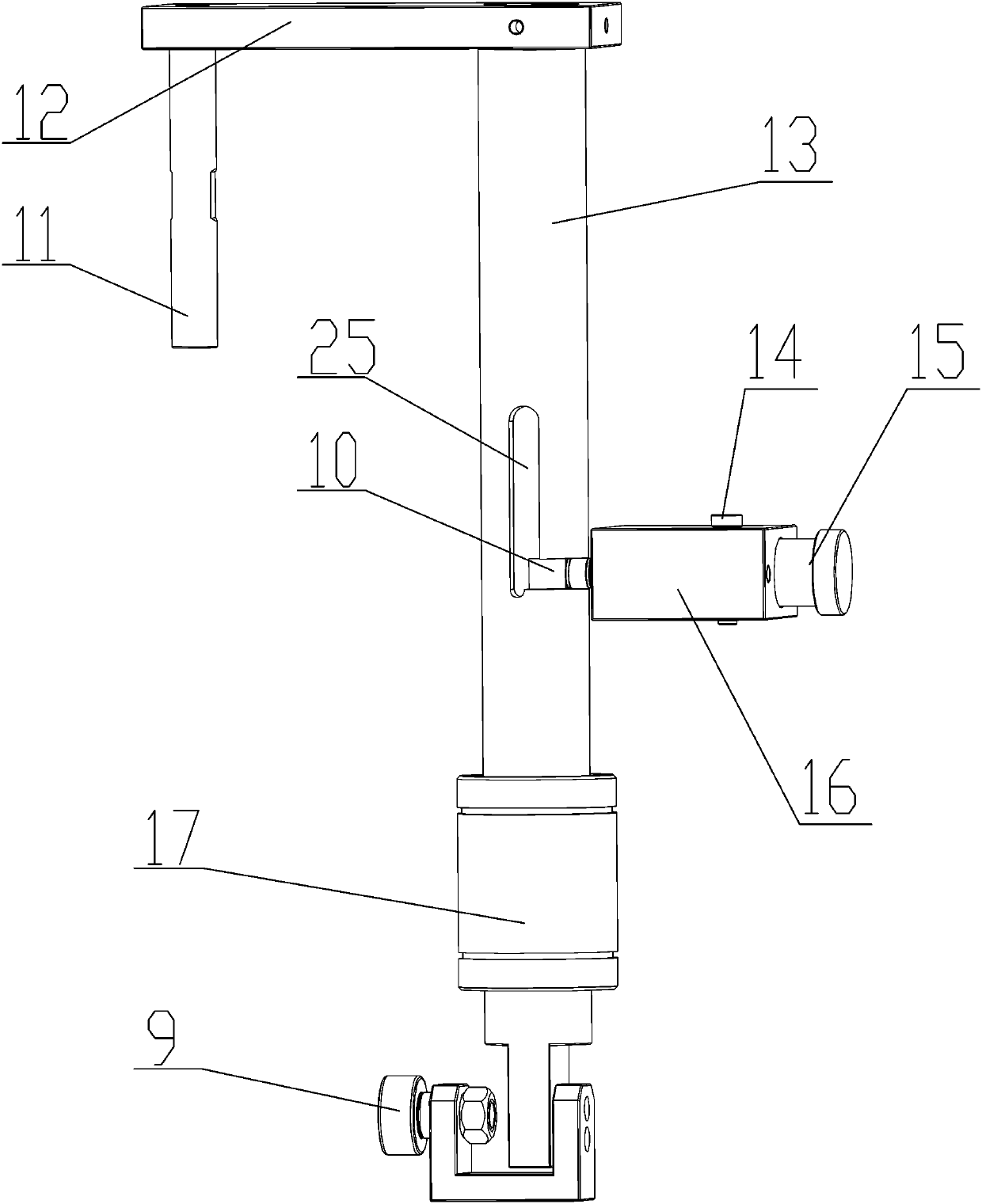
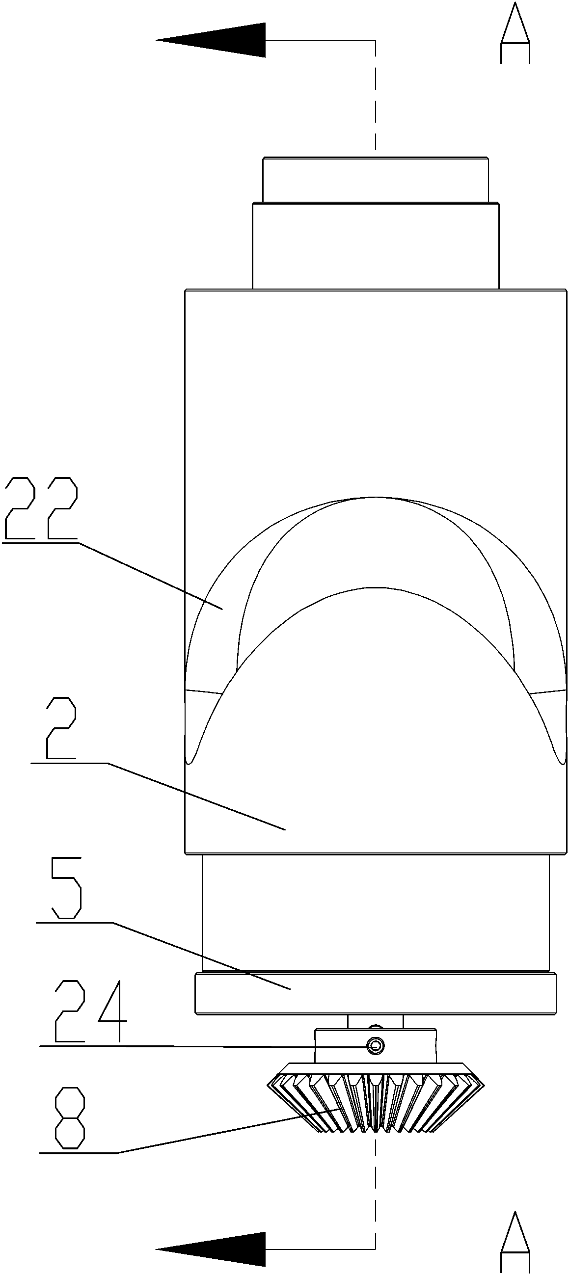
[0032] Such as Figure 1-4 As shown, the continuous intermittent rotary lifting working arm mechanism includes a support 1, the middle part of the support 1 is provided with a middle support plate 20, and a top support plate 26 is provided at its top, and the middle support plate 20 and the top A space cylindrical cam 2 is supported and installed between the support plates 26, and the bottom of the space cylindrical cam 2 is connected with a power device for driving it to rotate; the inside of the space cylindrical cam 2 is installed with a guide optical axis 13 through sliding fit, The bottom of the guide optical shaft 13 is equipped with a first bearing 9 through the optical shaft base 18, and the first bearing 9 is slidably driven with the cam chute 22 arranged on the space cylindrical cam 2, and drives the guide optical shaft 13 and the space Cylindrical cam 2 also realizes linear movement up and down relative to it while rotating together. By adopting the rotary lifting ...
Embodiment 2
[0044] The use method of any one of the continuous intermittent rotary lifting working arm mechanism, it comprises the following steps:
[0045] Step1: Turn the cam slide 22 and the guide groove 25 to the same side of the support 1;
[0046] Step2: Connect the motor to the power input shaft 6, drive the power input shaft 6 through the motor, drive the first bevel gear 7 through the power input shaft 6, and then drive the second bevel gear 8 through the first bevel gear 7, and drive the second bevel gear through the second bevel gear 8 drive space cylindrical cam 2;
[0047] Step3: The cam chute 22 of the spatial cylindrical cam 2 slides and fits with the first bearing 9 at the bottom of the optical guide shaft 13, and then drives the optical guide shaft 13 to rotate together with the spatial cylindrical cam 2 while moving up and down in a straight line relative to it;
[0048] Step4: By driving the guiding optical shaft 13, the rotating arm 12 on the top and the moving shaft ...
PUM
 Abstract
Description
Claims
Application Information
 - R&D
- Intellectual Property
- Life Sciences
- Materials
- Tech Scout
- Unparalleled Data Quality
- Higher Quality Content
- 60% Fewer Hallucinations
Browse by: Latest US Patents, China's latest patents, Technical Efficacy Thesaurus, Application Domain, Technology Topic, Popular Technical Reports.
© 2025 PatSnap. All rights reserved.Legal|Privacy policy|Modern Slavery Act Transparency Statement|Sitemap|About US| Contact US: help@patsnap.com


