

Constant pressure discharge system
A discharge system and regulating valve technology, which is applied in the pipeline system, mechanical equipment, gas/liquid distribution and storage, etc., can solve the problems of instrument analysis results fluctuation, instrument gas cannot be discharged, and affect instrument analysis, etc., to achieve simple structure and high pressure The effect of stabilizing and reducing the amount of supplementary air
- Summary
- Abstract
- Description
- Claims
- Application Information
AI Technical Summary
Problems solved by technology
Method used
Image

Examples
Embodiment
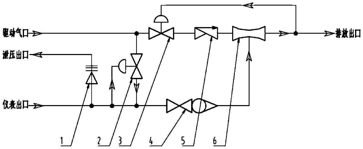
[0023] refer to figure 1 As shown, the present invention discloses a constant pressure discharge system, which includes a driving air port, a regulating valve 1 2, a regulating valve 2 3, a Venturi tube 6, a discharge outlet and a pressure relief outlet.
[0024] The driving gas port, the regulating valve 2 3 , the Venturi tube 6 and the discharge outlet are connected in sequence. The driving gas port is connected to the high-pressure driving gas source. The regulating valve 2 3 is connected with the discharge outlet signal for collecting the air pressure at the discharge outlet. The outlet of the meter is connected to the throat of the Venturi tube 6 . One end of the regulating valve one 2 is communicated between the driving gas port and the regulating valve two 3 , and the other end is communicated between the instrument outlet and the throat of the Venturi tube 6 . Regulating valve 1 and 2 are connected to the meter outlet signal, and are used to collect the air pressure...
PUM
 Abstract
Description
Claims
Application Information