
Optical cable fusion welding operation platform

A technology for operation table and optical cable, which is applied in the field of optical cable welding operation table, which can solve problems such as troublesome clamping process, difficult control of clamping force, damage to optical cable, etc., and achieve the effect of simple and convenient clamping process

Active Publication Date: 2019-06-14
金华八达集团有限公司 +1
View PDF7 Cites 3 Cited by
  • Summary
  • Abstract
  • Description
  • Claims
  • Application Information

AI Technical Summary

Problems solved by technology

[0004] The purpose of the present invention is to solve the problem that when the existing optical cable welding operation table clamps the optical cable, the clamping process is cumbersome and the clamping force is difficult to control, and it is easy to cause excessive clamping force and cause damage to the optical cable. An optical cable fusion operation table can effectively solve the above problems

Method used


Image

  • Optical cable fusion welding operation platform
  • Optical cable fusion welding operation platform
  • Optical cable fusion welding operation platform

Examples


Embodiment

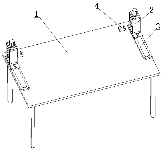
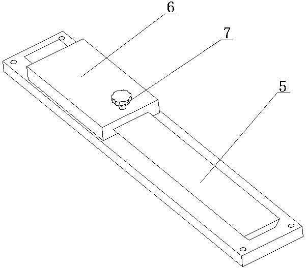
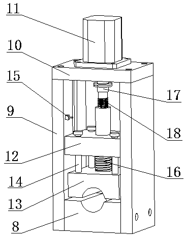
[0022] Example: such as Figure 1 to Figure 6 As shown, an optical cable fusion operation table includes a workbench 1 . Clamping devices 2 for fixing optical cables are respectively provided at both ends of the workbench 1 . The clamping device 2 is adjustably connected to the table top of the workbench 1 through the adjusting seat 3 . One side of each clamping device 2 is provided with a control module 4 for controlling the clamping device 2 . The control module 4 is provided with a control switch. The adjustment base 3 includes guide rails 5 fixed on both ends of the table top of the workbench 1 . The guide rail 5 is fixed on the table top of the workbench 1 through bolt connection. A slider 6 is movably connected to the guide rail 5 . The clamping device 2 is fixed on the upper end of the slider 6 . A fixing screw 7 for fixing the slider 6 is screwed on the slider 6 . When adjusting, first loosen the fixing screw 7, move the slide block 6 to the required position, a...


PUM


Abstract

The invention discloses an optical cable fusion welding operation platform. The optical cable fusion welding operation platform includes a work table, a clamping device for fixing an optical cable anda control module for controlling the clamping device, wherein the clamping device is adjustably connected to the two ends of the surface of the work table through an adjusting seat, the clamping device includes a clamping base and a moving clamping part, the moving clamping part is arranged above the clamping base and is driven by a motor to move relative to the moving clamping base, the motor iselectrically connected with the control module, the moving clamping part includes a moving plate, the moving plate is connected with the motor in a transmission mode, clamping blocks are arranged below the moving plate and directly face the clamping base, the moving plate and the clamping blocks are connected through springs, a stroke control mechanism is further arranged between the moving plateand the clamping blocks, and the relative moving distance of the moving plate and the clamping blocks is controlled through the stroke control mechanism. According to the optical cable fusion weldingoperation platform, when the optical cable is fastened and fixed, the magnitude of clamping force can be effectively controlled, and the problem that in an existing manual clamping device, the optical cable is damaged due to the fact that the size of the clamping force is difficult to control is avoided.

Description

technical field [0001] The invention relates to an optical cable welding equipment, in particular to an optical cable welding operation table. Background technique [0002] Fiber optic cables need to be spliced ​​on the splicing table. When performing welding work, the optical cable needs to be clamped by the clamping device arranged at both ends of the welding operation table, and then the optical cable is welded by the optical cable welding machine. However, the existing clamping device is manually clamped, and its disadvantages are that the clamping process is cumbersome, and the clamping force is difficult to control, which may cause damage to the optical cable due to excessive clamping force. [0003] For example: Chinese Patent Publication No. CN 202433556 U, the name of the utility model is a portable optical fiber fusion splicing operation table, which is composed of a table top, a bracket, and a clamper. The utility model clamps and fixes the optical cable through ...

Claims


Application Information

Patent Timeline
Patent Type & Authority Applications(China)
IPC IPC(8): G02B6/255
Inventor 孔晓峰吴秀松张文杰黄穗金航况建国毛伟民
Owner 金华八达集团有限公司
Learn More