Novel speed-adjustable cylindrical permanent-magnet eddy-current coupler

A permanent magnet eddy current and coupling technology, which is used in the control of mechanical energy, electrical components, electromechanical devices, etc., can solve the problems of large speed regulating mechanism, waste of magnetic pole action area, unfavorable torque transmission, etc., and is conducive to torque stability. the effect of transmission

Pending Publication Date: 2019-06-14
SICHUAN UNIV
View PDF4 Cites 0 Cited by
  • Summary
  • Abstract
  • Description
  • Claims
  • Application Information

AI Technical Summary

Problems solved by technology

The two kinds of speed regulating mechanisms realize the speed regulation by moving the rotor of the disc structure permanent magnet eddy current coupling along the axis, and then changing the thickness of the air gap magnetic field. This driving method has a large axial force, which has a great impact on bearings and other components. Larger damage, and for the patent CN105449981A, it is necessary to push the entire motor to move, the speed regulating mechanism requires a large force, and the cost is high, while the patent CN206628970U adopts manual speed regulation, which is not practical
Patent CN103401396B and patent CN202160092 respectively realize a cylindrical structure adjustable speed permanent magnet eddy current coupling. Both patents use the speed regulating mechanism to drive the rotor to move along the axis, so that the meshing area of ​​the inner and outer rotors is changed to realize the adjustment. On the one hand, this speed regulation method will cause a waste of magnetic pole action area. On the other hand, due to the asymmetry of the inner and outer rotor structures after speed regulation, there will be axial force after speed regulation. At the same time, the current speed-adjustable permanent magnet eddy current Due to the existence of the speed regulating mechanism, the coupling generally has eccentric force, which is not conducive to the transmission of torque

Method used


Image

  • Novel speed-adjustable cylindrical permanent-magnet eddy-current coupler
  • Novel speed-adjustable cylindrical permanent-magnet eddy-current coupler
  • Novel speed-adjustable cylindrical permanent-magnet eddy-current coupler

Examples


Embodiment Construction

[0016] The specific embodiments of the present invention will be described below in conjunction with the accompanying drawings.

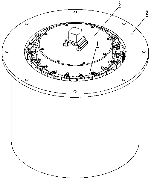
[0017] figure 1 It is a structural schematic diagram of a new adjustable speed cylindrical permanent magnet eddy current coupling designed by the present invention, which is composed of an inner rotor 1, an outer rotor 2 and a speed regulating mechanism 3.

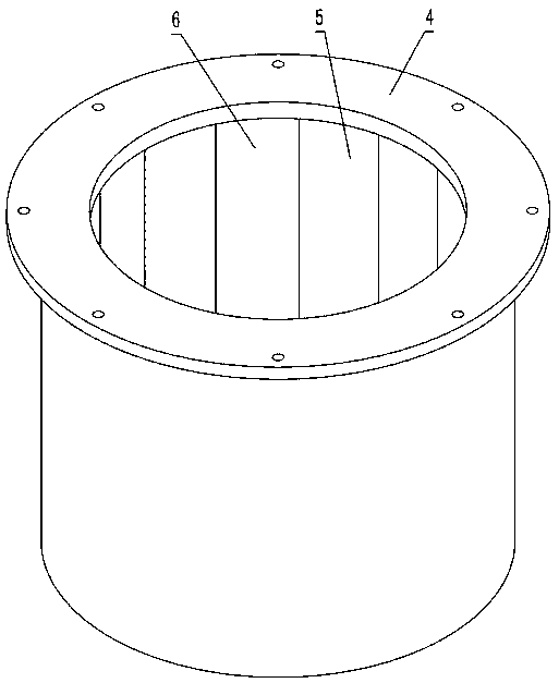
[0018] figure 2 It is a structural schematic diagram of the outer rotor of a new type adjustable speed cylindrical permanent magnet eddy current coupling designed by the present invention, which is composed of an outer rotor base 4, an N-type permanent magnet 5, and an S-type permanent magnet 6. The outer rotor base 4 is a cylindrical structure with an inlaid groove inside the cylinder, and one end of the outer rotor base 4 is designed with a flange structure for connecting with the input shaft. N-type permanent magnets 5 and S-type permanent magnets 6 are alternately inlaid in the inlay groo...


PUM


Abstract

The invention relates to a novel speed-adjustable cylindrical permanent-magnet eddy-current coupler. The novel speed-adjustable cylindrical permanent-magnet eddy-current coupler comprises an inner rotor 1 and an outer rotor 2, wherein a permanent magnet 5 is embedded onto the outer rotor 2, the inner rotor 1 is of a squirrel cage structure, a speed regulation mechanism 3 is arranged on the inner rotor, an inner rotor guide strip 3 moves along a radial direction through driving the speed regulation mechanism 3 by a motor 21, the thickness adjustment of an air gap magnetic field is achieved, thesize of a magnetic field at a position where the guide strip 8 is located is further changed, and the speed regulation function is achieved. Compared with a traditional speed-adjustable permanent-magnet eddy-current coupler, the novel speed-adjustable cylindrical permanent-magnet eddy-current coupler is compact in structure, no eccentric force is generated, the problem of an axial force brought by structure asymmetry after speed regulation is prevented, and the novel speed-adjustable cylindrical permanent-magnet eddy-current coupler has wide application prospect.

Description

technical field [0001] The invention belongs to the technical field of magnetic drive, and relates to a permanent magnet eddy current coupling, in particular to a novel speed-adjustable cylindrical permanent magnet eddy current coupling. Background technique [0002] The permanent magnet coupling is a component that uses the magnetic force generated by the permanent magnet material to realize the non-contact transmission of torque. Compared with traditional mechanically connected couplings, permanent magnet couplings have the advantages of smooth operation, no leakage, and overload protection. Among them, the permanent magnet eddy current coupling has asynchronous characteristics in the speed, can realize the adjustment of the output speed and soft start and other functions, and can also avoid the harmonic pollution of the power grid caused by the frequency conversion speed regulation of the motor, so it has been used in industrial production. It has been widely promoted an...

Claims


Application Information

Patent Timeline
IPC IPC(8): H02K51/00H02K7/116
Inventor 熊志强袁靖刘伟姚进魏文龙张世友唐斯琪
Owner SICHUAN UNIV
Why Eureka
Try Eureka