Control method and device of DC/DC converter
A control method and converter technology, which can be used in output power conversion devices, conversion equipment without intermediate conversion to AC, control/regulation systems, etc., can solve the problem of thermal imbalance between switching tubes, large effective current, and large temperature difference. And other issues
- Summary
- Abstract
- Description
- Claims
- Application Information
AI Technical Summary
Problems solved by technology
Method used
Image
Examples
Embodiment 1
[0070] Figure 4 The flow chart of the control method of the DC / DC converter provided by Embodiment 1 of the present invention, such as Figure 4 As shown, the execution subject of the DC / DC converter control method provided in this embodiment is the DC / DC converter control device, and the DC / DC converter control method provided in this embodiment includes the following steps.
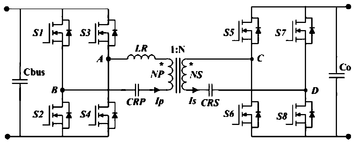
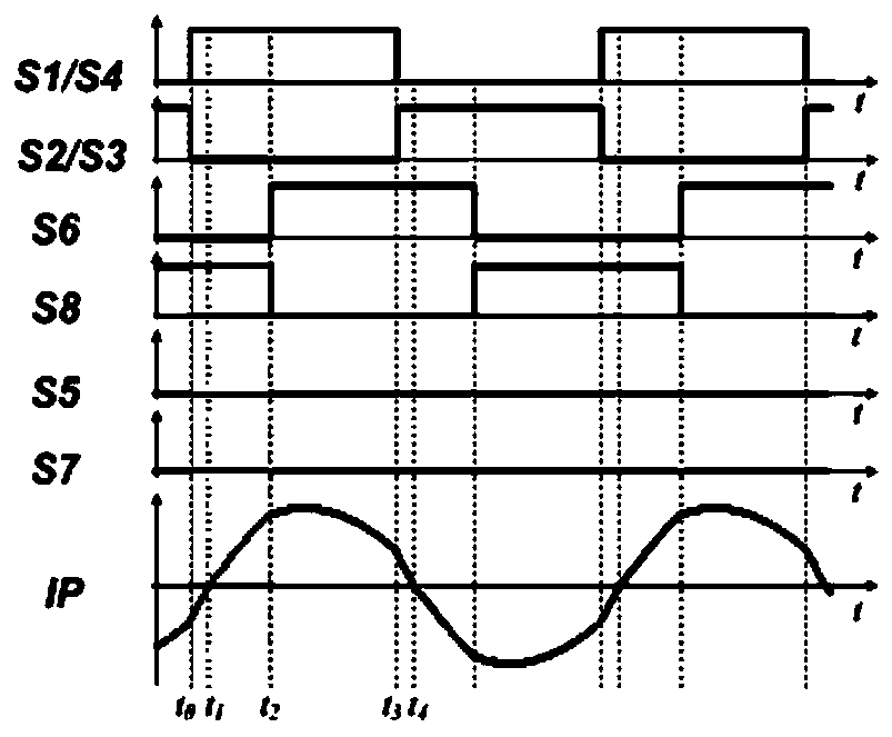
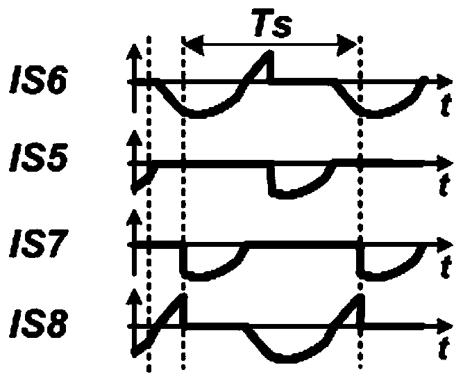
[0071] Step 101, provide the sixth signal, the fifth signal, the seventh signal and the eighth signal, the switching frequency of the sixth signal, the fifth signal, the seventh signal and the eighth signal is the switching frequency of the driving signal of each switching tube on the primary side Half, the phase difference between adjacent signals of the sixth signal, the fifth signal, the seventh signal and the eighth signal is a preset angle, and the phase difference between the sixth signal and the driving signal of the first switch tube is a phase shift angle.
[0072] In this embodiment, the DC / ...
Embodiment 2
[0087] Figure 5 The flow chart of the control method of the DC / DC converter provided by Embodiment 2 of the present invention, such as Figure 5 As shown, the DC / DC converter control method provided in this embodiment is based on the DC / DC converter control method provided in Embodiment 1 of the present invention, and the sixth signal, the fifth signal, and the seventh signal in step 101 are The phase difference between the adjacent signals of the eighth signal and the eighth signal is a further refinement of the preset angle, and the sixth signal, the fifth signal, the seventh signal and the eighth signal are used as driving signals. Then, the control method of the DC / DC converter provided in this embodiment includes the following steps.
[0088] Step 201, provide the sixth signal, the fifth signal, the seventh signal and the eighth signal, the switching frequency of the sixth signal, the fifth signal, the seventh signal and the eighth signal is the switching frequency of t...
Embodiment 3
[0100] Figure 7 The flow chart of the control method of the DC / DC converter provided by Embodiment 3 of the present invention, such as Figure 7 As shown, the DC / DC converter control method provided in this embodiment is based on the DC / DC converter control method provided in Embodiment 1 of the present invention, and the sixth signal, the fifth signal, and the seventh signal in step 101 are The phase difference between the adjacent signals of the eighth signal and the eighth signal is a further refinement of the preset angle, and the sixth signal, the fifth signal, the seventh signal and the eighth signal are used as driving signals. Then, the control method of the DC / DC converter provided in this embodiment includes the following steps.
[0101] Step 301, provide the sixth signal, the fifth signal, the seventh signal and the eighth signal, the switching frequency of the sixth signal, the fifth signal, the seventh signal and the eighth signal is the switching frequency of t...
PUM
 Abstract
Description
Claims
Application Information
 - R&D
- Intellectual Property
- Life Sciences
- Materials
- Tech Scout
- Unparalleled Data Quality
- Higher Quality Content
- 60% Fewer Hallucinations
Browse by: Latest US Patents, China's latest patents, Technical Efficacy Thesaurus, Application Domain, Technology Topic, Popular Technical Reports.
© 2025 PatSnap. All rights reserved.Legal|Privacy policy|Modern Slavery Act Transparency Statement|Sitemap|About US| Contact US: help@patsnap.com


