Multi-layer coextrusion blown-film die

A multi-layer co-extrusion and machine head technology, which is applied in the field of multi-layer co-extrusion blown film head, can solve the problems of large volume, difficulty, and aggravated sealing of the lower part of the machine head, and achieve the risk of material denaturation, peak cutting, valley filling, Reduce the degree of unequal exclusion and protect the effect of extrusion pressure

Active Publication Date: 2019-06-18
GUANGDONG JINMING MACHINERY
View PDF4 Cites 2 Cited by
  • Summary
  • Abstract
  • Description
  • Claims
  • Application Information

AI Technical Summary

Problems solved by technology

Specifically, the outermost material (generally a functional layer) with less material and high material requirements has the longest radial runner path, which means that the pressure loss during the flow of molten material is the largest and the risk of material denaturation is the greatest, while The material in the middle layer (generally the skeleton layer) with large materials and low material requirements has a radial runner path shorter than that of the outermost layer material (functional layer), which means that the pressure loss in the flow process of the skeleton layer material is small, and the material The risk of denaturation is small; and when the molten materials of each layer meet during the extrusion process, the extrusion pressure of the outermost layer (functional layer) with the smallest dosage and severe pressure loss is low and unstable, and is easily affected by the large dosage and small pressure loss. The unfair extrusion of the molten material (skeleton layer) in the middle layer leads to relatively poor extrusion quality of the outermost layer material, resulting in unstable function of the functional layer, so it seems unreasonable
[0013] 2. The eccentric position of the lower part of the machine head needs to arrange multiple circles of holes from the inside to the outside. Each circle of holes is the radial branch channel of one layer of material flow channel. The same circle of holes is arranged on the same circle, and the holes of different circles are arranged on the same circle. Arranged along the radial direction of the machine head, the holes are arranged in concentric circles, so the lower part of the machine head needs to have a wide enough radius to be able to arrange multiple circles of holes from the inside to the outside, which means that the lower part of the machine head is large in size, It consumes a lot of alloy steel, takes a long time to warm up during work, and consumes a lot of energy, which will aggravate the difficulty of sealing, and the precision of the sealing interface is quite high.

Method used


Image

  • Multi-layer coextrusion blown-film die
  • Multi-layer coextrusion blown-film die
  • Multi-layer coextrusion blown-film die

Examples


Embodiment Construction

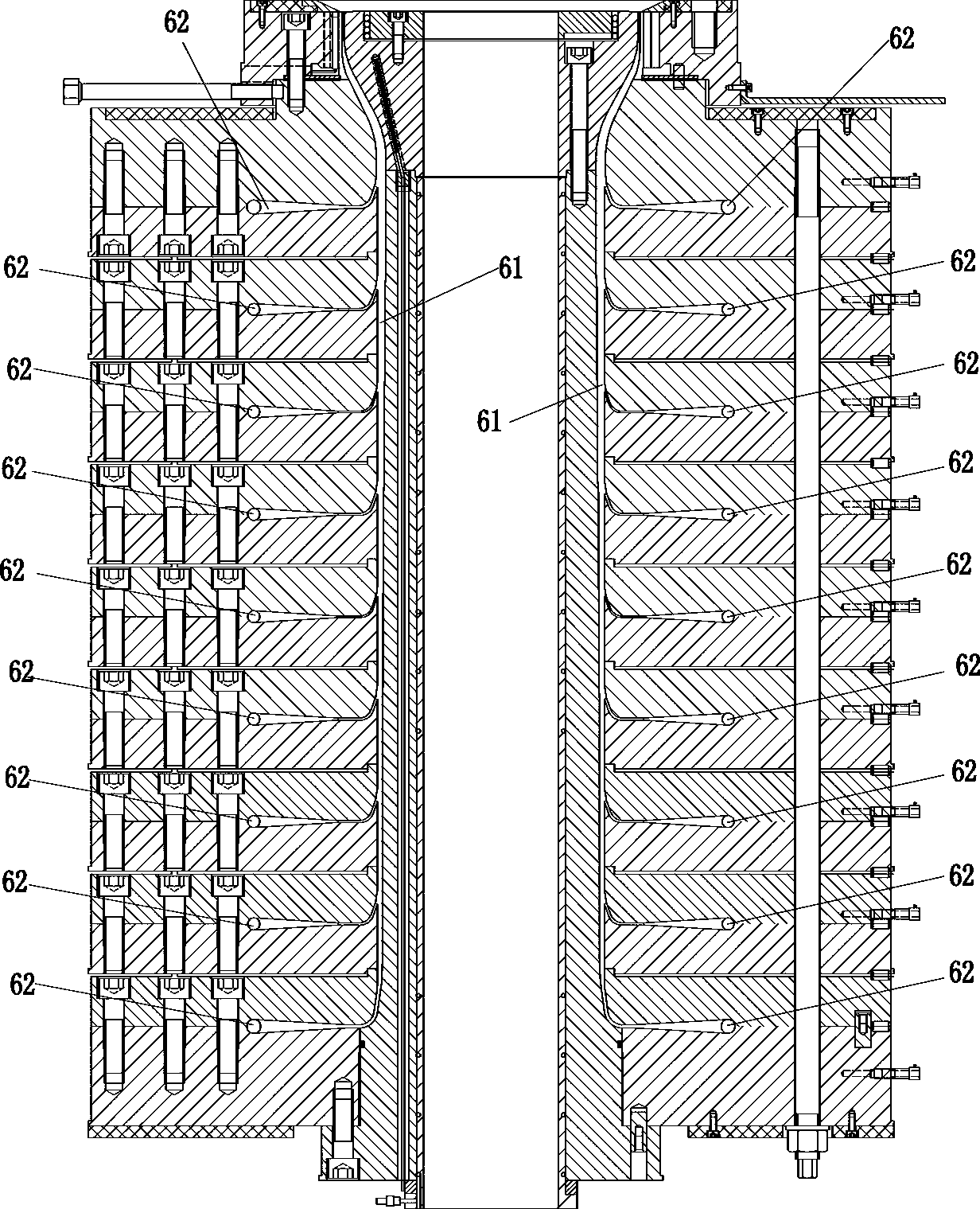
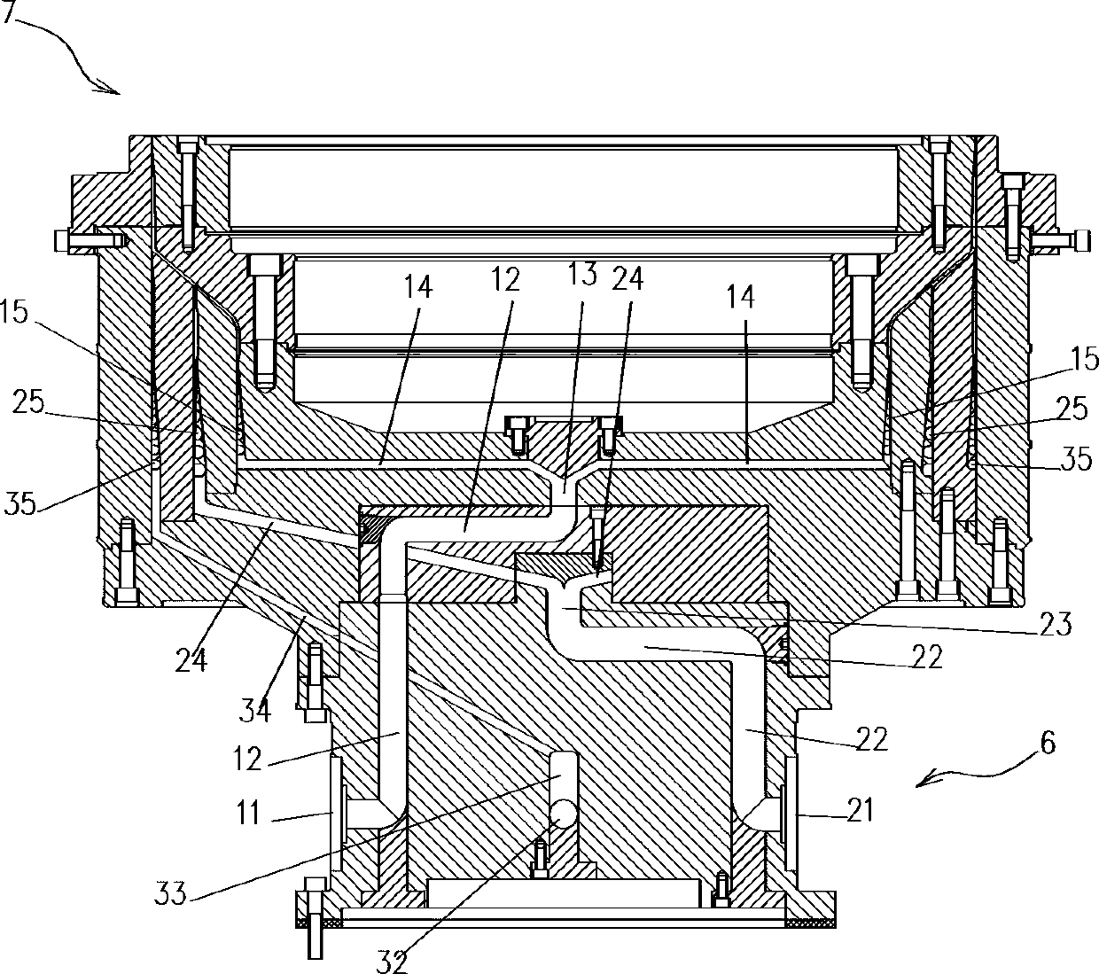
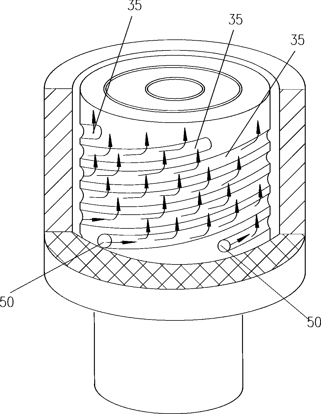
[0054] Figure 5 , Figure 6 , Figure 7 , Figure 8 , Figure 9 , Figure 10 , Figure 11 , Figure 12 , Figure 13 The multi-layer co-extrusion blown film head shown is a five-layer co-extrusion blown film head, including five sets of material flow channel systems, each set of material flow channel systems is used to guide the flow of a corresponding layer of material; each A set of material flow channel system includes a material inlet, an eccentric main channel, a central main channel, multiple radial branch channels, and multiple spiral flow channels;

[0055] Specifically, the first set of material flow channel system includes a feed inlet 11, an eccentric main channel 12, a central main channel 13, a plurality of radial branch channels 14, and a plurality of spiral flow channels 15, such as Figure 7 , Figure 14 , Figure 19 As shown; the second set of material flow channel system includes a feed inlet 21, an eccentric main channel 22, a central main channel ...


PUM


Abstract

The invention relates to a multi-layer coextrusion blown-film die which comprises N sets of material runner systems. Each set of material runner system comprises a feed inlet, an eccentric main runner, a center main runner, multiple radial sub-runners, and multiple spiral runners. Except for the material runner system on the innermost layer, each radial sub-runner of each of the rest sets of material runner systems comprises a section of radial sub-runner telecentric section, a section of radial sub-runner vertical section and a section of radial sub-runner pericenter section; the number of the radial sub-runner vertical sections of the whole die is totally 8x(N-1); the horizontal distances from the 8x(N-1) radial sub-runner vertical sections to the central axes of the die are equal; and the vertical position of the center main runner of the material runner system on the outermost layer is higher than the center main runner of the material runner system on the middlemost layer. According to the multi-layer coextrusion blown-film die provided by the invention, the diameter of the lower part is small, and a most suitable scheme of one-to-one corresponding combination between the spiral runners and the center main runners can be flexibly selected optimally.

Description

technical field [0001] The invention belongs to the technical field of film blowing equipment, and in particular relates to a multi-layer co-extrusion film blowing machine head. Background technique [0002] When the multi-layer co-extrusion blown film machine is working, the molten plastic materials of each layer are flow-distributed and finally merged into a circular die for extrusion to obtain a cylindrical multi-layer co-extruded composite plastic film. Composite plastic films contain multiple layers of plastic materials compounded together. After the cylindrical composite plastic film is cut, it becomes a planar film, in which the layer of plastic material originally located on the outermost layer of the cylindrical composite plastic film becomes the surface layer (such as the upper surface) of the planar film, and The innermost layer of plastic material in the cylindrical composite plastic film also becomes the surface layer (such as the lower surface) of the planar f...

Claims


Application Information

Patent Timeline
Patent Type & Authority Applications(China)
IPC IPC(8): B29C55/28B29C48/18B29C48/32
Inventor 李浩王侠武黄一帆蔡成鹏
Owner GUANGDONG JINMING MACHINERY
Why Eureka
Try Eureka