Fluidifying tank, blast furnace coal injecting device and system and a control method

A blast furnace coal injection and fluidization device technology, which is applied to blast furnaces, blast furnace details, blast furnace parts, etc., can solve the problems of electronic scale impact, increased injection volume, and difficulty in eliminating, so as to improve measurement accuracy and reduce energy consumption , to maintain a stable effect

Pending Publication Date: 2019-06-18
CISDI RES & DEV CO LTD
View PDF0 Cites 0 Cited by
  • Summary
  • Abstract
  • Description
  • Claims
  • Application Information

AI Technical Summary

Problems solved by technology

Blast furnace injection volume is generally 10-100t / h (instantaneous injection volume 2.8-28kg / s), generally requires instantaneous fluctuation within 5%, electronic scale accuracy is not more than 2kg, so the electronic scale accuracy of the original process and instantaneous injection Blowing accuracy requires overlapping, it is difficult to achieve accurate measurement of blowing volume
[0004] Secondly, since the electronic scales of all the spray tanks are installed on the same platform beam, it is necessary to complete the 10-50t / h powder loading within 5-6 minutes during the coal loading process, which will inevitably cause impact on the electronic scales in the spray tanks, resulting in blowing The illusion of increasing the amount, while destroying the balance between process parameters
[0005] Once again, due to the pressurization of many flexible connections connected to the blowing tank, a large internal stress is formed, which is difficult to measure and eliminate, which has a great impact on the weighing process of the electronic scale
[0006] Finally, because the coal injection system using quantitative feeding is often in operation, because the pulverized coal is in a static state in the quantitative feeder, it needs to consume a large amount of high-pressure gas to accelerate before entering the pipeline, resulting in increased energy consumption and it is difficult to achieve flow. state dense phase transport

Method used


Image

  • Fluidifying tank, blast furnace coal injecting device and system and a control method
  • Fluidifying tank, blast furnace coal injecting device and system and a control method
  • Fluidifying tank, blast furnace coal injecting device and system and a control method

Examples


Embodiment Construction

[0030] Embodiments of the present invention are described below through specific examples, and those skilled in the art can easily understand other advantages and effects of the present invention from the content disclosed in this specification. The present invention can also be implemented or applied through other different specific implementation modes, and various modifications or changes can be made to the details in this specification based on different viewpoints and applications without departing from the spirit of the present invention. It should be noted that, in the case of no conflict, the following embodiments and features in the embodiments can be combined with each other.

[0031] It should be noted that the diagrams provided in the following embodiments are only schematically illustrating the basic ideas of the present invention, and only the components related to the present invention are shown in the diagrams rather than the number, shape and shape of the compo...


PUM


Abstract

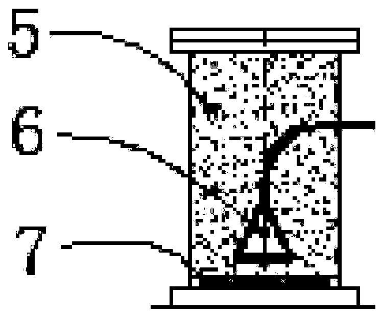
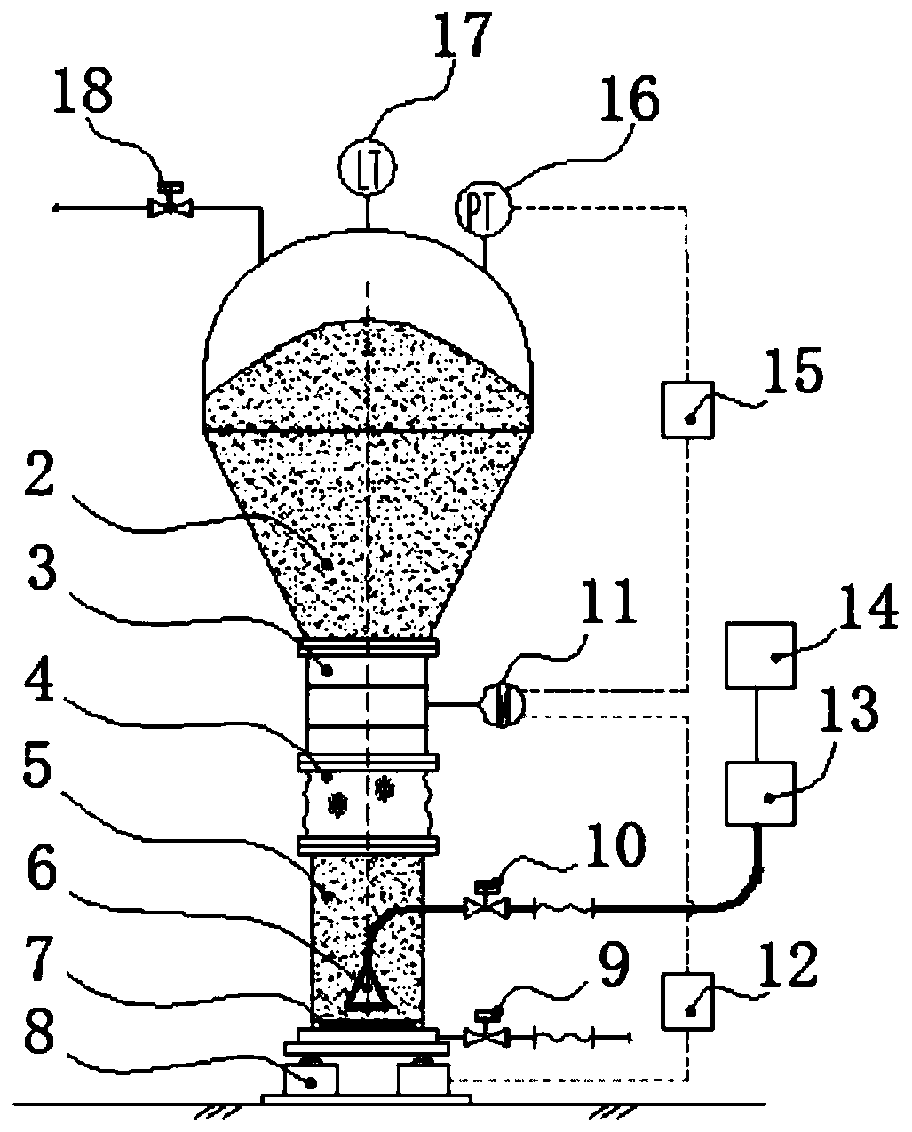
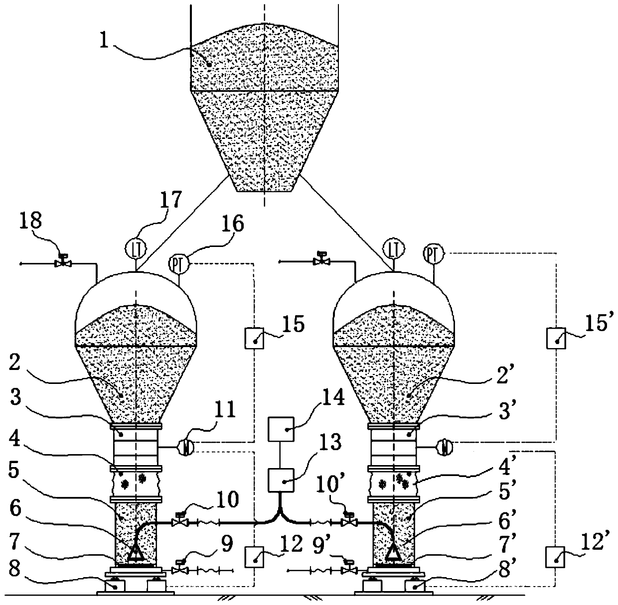
The invention discloses a blast furnace coal injecting device. The blast furnace coal injecting device comprises an injecting tank, a quantitative feeding device, and a quantitative feeding device driving mechanism. The blast furnace coal injecting device is characterized by further comprising a fluidifying tank and a weighing device; and the fluidifying tank is arranged on the weighing device, communicates with the quantitative feeding device, and is flexibly connected with the quantitative feeding device. The blast furnace coal injecting device is provided with the fluidifying tank and the weighing device in an outlet of the quantitative feeding device, and adopts a coal injecting quantity two-stage control method to achieve the purpose of further improving the injecting quantity metering precision.

Description

technical field [0001] The invention relates to a pneumatic conveying system for bulk materials, in particular to a blast furnace coal injection device, system and control method. Background technique [0002] At present, most blast furnace coal injection systems adopt tank-merging injection technology. 2-4 injection tanks correspond to a blast furnace. The injection tanks are installed on the same platform beam, and three electronic scales are installed under the injection tanks. Change to calculate the injection volume. The current blast furnace coal injection system mainly has the following problems: [0003] First of all, the accuracy of the electronic scale of the injection tank cannot meet the requirements of the accuracy of blast furnace injection, resulting in excessive errors. The volume of the blowing tank is in the range of 20 to 100m3, and the powder filling capacity is in the range of 10 to 50t / h. The accuracy of the electronic scale in this range is generally...

Claims


Application Information

Patent Timeline
Patent Type & Authority Applications(China)
IPC IPC(8): C21B5/00C21B7/00
Inventor 何海熙马云峰王贤赵运建钟星立王刚
Owner CISDI RES & DEV CO LTD
Why Eureka
Try Eureka