Precise transmission speed reducer

A technology of precision transmission and reducer, which is applied in the direction of transmission, transmission parts, gear transmission, etc., can solve the problems of low overall efficiency of meshing gap and affecting power generation efficiency, etc., and achieve high bearing capacity, small size and large transmission ratio Effect

Inactive Publication Date: 2019-06-18
ZHONGNENG TIANJIN INTELLIGENT TRANSMISSION EQUIP CO LTD
View PDF5 Cites 7 Cited by
  • Summary
  • Abstract
  • Description
  • Claims
  • Application Information

AI Technical Summary

Problems solved by technology

[0002] At present, the drive of domestic large-scale solar thermal power tower mirror field heliostats mainly adopts worm drive, but because its teeth basically belong to friction drive, the meshing gap gradually increases, and the total efficiency is as low as 20%, which seriously affects the power generation efficiency, and There is currently no reducer that can effectively adapt to the configuration of important joints of large and heavy industrial robots in the robot market, and there is a gap in the market for such products

Method used


Image

  • Precise transmission speed reducer
  • Precise transmission speed reducer

Examples


Embodiment 1

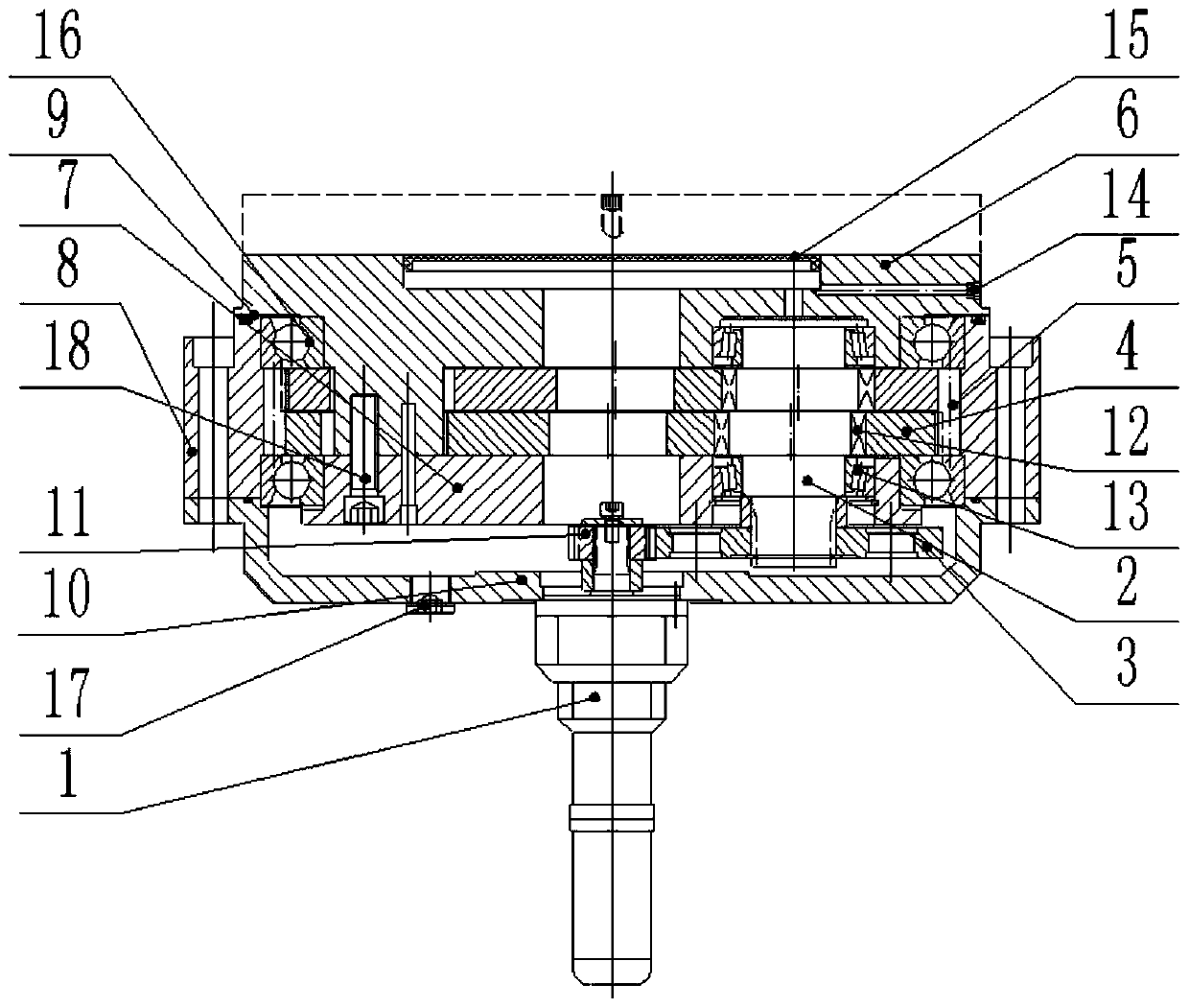
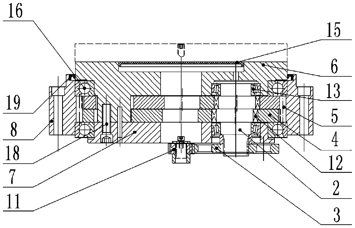
[0021] see figure 2 , the present invention includes an input gear shaft 11, a crankshaft 2 is arranged on one side of the input gear shaft 11, and the crankshaft 2 is provided with an output disk 6, two cycloidal wheels 4, a rigid disk 7, a planetary There are two eccentric parts in the middle of the gear 3 and the crankshaft 2;

[0022] Tapered roller bearings 13 are arranged between the output disk 6 and the upper end of the crankshaft 2, and between the rigid disk 7 and the lower end of the crankshaft 2. The cycloidal wheel 4 is placed in a circumferential direction with a difference of 180°, and a roller bearing 12 is arranged between the cycloidal wheel 4 and the crankshaft 2, and the planetary gear 3 is fixed to the crankshaft 2 through the inner teeth, and is connected to the input gear shaft 11. The gears are meshed, and the rigid disk 7 and the output disk 6 are fixedly connected by fastening screws 18;

[0023] It also includes pin gear housing 8, pin gear housin...

Embodiment 2

[0025] see figure 2 , the present invention includes an input gear shaft 11, a crankshaft 2 is arranged on one side of the input gear shaft 11, and the crankshaft 2 is provided with an output disk 6, two cycloidal wheels 4, a rigid disk 7, a planetary There are two eccentric parts in the middle of the gear 3 and the crankshaft 2;

[0026] Tapered roller bearings 13 are arranged between the output disk 6 and the upper end of the crankshaft 2, and between the rigid disk 7 and the lower end of the crankshaft 2. The cycloidal wheel 4 is placed in a circumferential direction with a difference of 180°. A roller bearing 12 is arranged between the cycloidal wheel 4 and the crankshaft 2. The planetary gear 3 is fixed to the crankshaft 2 and meshed with the gear of the input gear shaft 11. The rigid disc 7 and the output disk 6 are fixed by fastening screws 18;

[0027] It also includes pin gear housing 8, pin gear housing 8 meshes with cycloidal wheel 4 through pin gear pin 5 provid...

Embodiment 3

[0033] see figure 1 , the present invention includes an input gear shaft 11, a crankshaft 2 is arranged on one side of the input gear shaft 11, and the crankshaft 2 is provided with an output disk 6, two cycloidal wheels 4, a rigid disk 7, a planetary There are two eccentric parts in the middle of the gear 3 and the crankshaft 2;

[0034] Tapered roller bearings 13 are arranged between the output disk 6 and the upper end of the crankshaft 2, and between the rigid disk 7 and the lower end of the crankshaft 2. The cycloidal wheel 4 is placed in a circumferential direction with a difference of 180°. A roller bearing 12 is arranged between the cycloidal wheel 4 and the crankshaft 2. The planetary gear 3 is fixed to the crankshaft 2 and meshed with the gear of the input gear shaft 11. The rigid disc 7 and the output disk 6 are fixed by fastening screws 18;

[0035] It also includes pin gear housing 8, pin gear housing 8 meshes with cycloidal wheel 4 through pin gear pin 5 provide...


PUM


Abstract

The invention relates to a precise transmission speed reducer. The speed reducer comprises an input gear shaft, a crankshaft is arranged on one side of the input gear shaft, the crankshaft is sequentially provided with an output disc, two cycloidal gears, a rigid disc and a planetary gear in a penetrating manner from top to bottom, two eccentric parts are arranged in the middle of the crankshaft,conical roller bearings are arranged between the output disc and the upper end of the crankshaft and between the rigid disc and the lower end of the crankshaft, the two cycloidal gears are located onthe periphery of the two eccentric parts of the crankshaft, the cycloidal gears are placed in the direction that the circumference difference is 180 degrees, roller bearings are arranged between the cycloidal gears and the crankshaft, the planetary gear is fixed to the crankshaft, the planetary gear is engaged with the gear of the input gear shaft, and the rigid disc is fixed to the output disc. Aneedle gear shell is included, the needle gear shell is engaged with the cycloidal gears through needle gear pins arranged on the inner circumference, and angular contact ball bearings are arranged between the needle gear shell and the rigid disc and between the needle gear shell and the output disc. The speed reducer is large in transmission ratio, high in bearing capacity, high in transmissionprecision, high in transmission efficiency, long in service life and small in return difference.

Description

technical field [0001] The invention relates to the technical field of reducers, in particular to a precision transmission reducer. Background technique [0002] At present, the drive of domestic large-scale solar thermal power tower mirror field heliostats mainly adopts worm drive, but because its teeth basically belong to friction drive, the meshing gap gradually increases, and the total efficiency is as low as 20%, which seriously affects the power generation efficiency, and There is currently no reducer that can effectively adapt to the configuration of important joints of large and heavy industrial robots in the robot market, and there is a gap in the market for such products. Contents of the invention [0003] The invention aims to solve the deficiencies of the prior art, and provides a precision transmission reducer with large transmission ratio, high bearing capacity, high transmission precision, high transmission efficiency, long service life and small hysteresis....

Claims


Application Information

Patent Timeline
Patent Type & Authority Applications(China)
IPC IPC(8): F16H1/28F16H57/021F16H57/023F16H57/04F16H57/029F16H57/031
Inventor 黄怀斌李文涛李剑利王鹏飞刘宗华许国军张庭勋
Owner ZHONGNENG TIANJIN INTELLIGENT TRANSMISSION EQUIP CO LTD
Why Eureka
Try Eureka