Determining and applying a voltage to a piezoelectric actuator

a piezoelectric actuator and voltage technology, applied in the field of piezoelectric actuators, can solve the problems of time and power consumption, difficult implementation, hysteresis and piezo creep, etc., and achieve the effect of small power consumption

Active Publication Date: 2021-10-28
POLIGHT ASA
View PDF0 Cites 0 Cited by
  • Summary
  • Abstract
  • Description
  • Claims
  • Application Information

AI Technical Summary

Benefits of technology

[0006]It is an object of the invention to provide a method and a system for open loop compensation for creep and / or hysteresis in PEAs that is particularly suited for actuator systems that need to operate fast and with small power consumption.
[0016]The method according to the first aspect provides the advantage that the calculated relation d(tt) between the displacement measure and transition time at the same time characterises the individual PEA, has no hysteresis, and does not vary with time or usage of the PEA. This is in contrast to the relations used to calculate d(tt), which both have significant hysteresis and are both prone to change with time and usage history. By determining a current version of one of these relations at a later stage, the other can be derived using d(tt), thus compensating for the changes. It is important to note that the transition time is one of more related properties of the PEA that can be used for this purpose. The capacitance of a PEA is a function of the geometry and the dielectric permittivity of the material, and is thus more or less a material parameter, but not necessarily trivial to measure without a sophisticated measurement set-up. The transition time (the time to charge or discharge the PEA) is strongly correlated with capacitance, and can be used as a method to measure the capacitance.

Problems solved by technology

Hysteresis and piezo creep are well known problems of PEAs.
The price, however, is time and power consumption which are disadvantageous for many applications.
These methods are disadvantageous in that they are difficult to implement in ASICs.

Method used


Image

  • Determining and applying a voltage to a piezoelectric actuator
  • Determining and applying a voltage to a piezoelectric actuator
  • Determining and applying a voltage to a piezoelectric actuator

Examples


Embodiment Construction

[0058]In the following, various aspects and embodiments of the invention are described in relation to a PEA forming part of an adjustable focus lens assembly in a camera module.

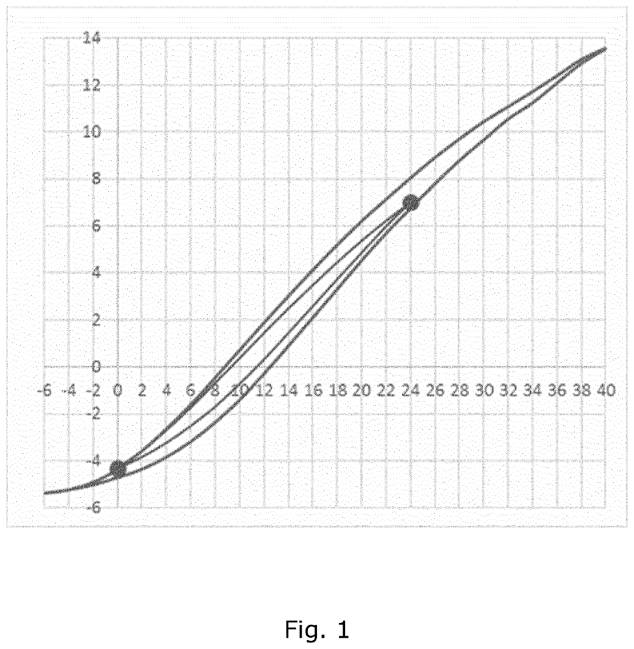
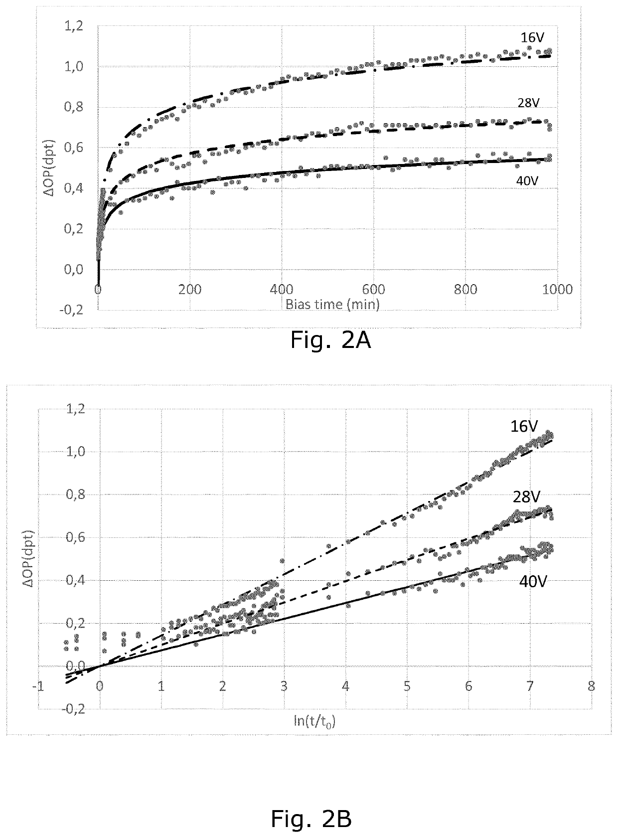
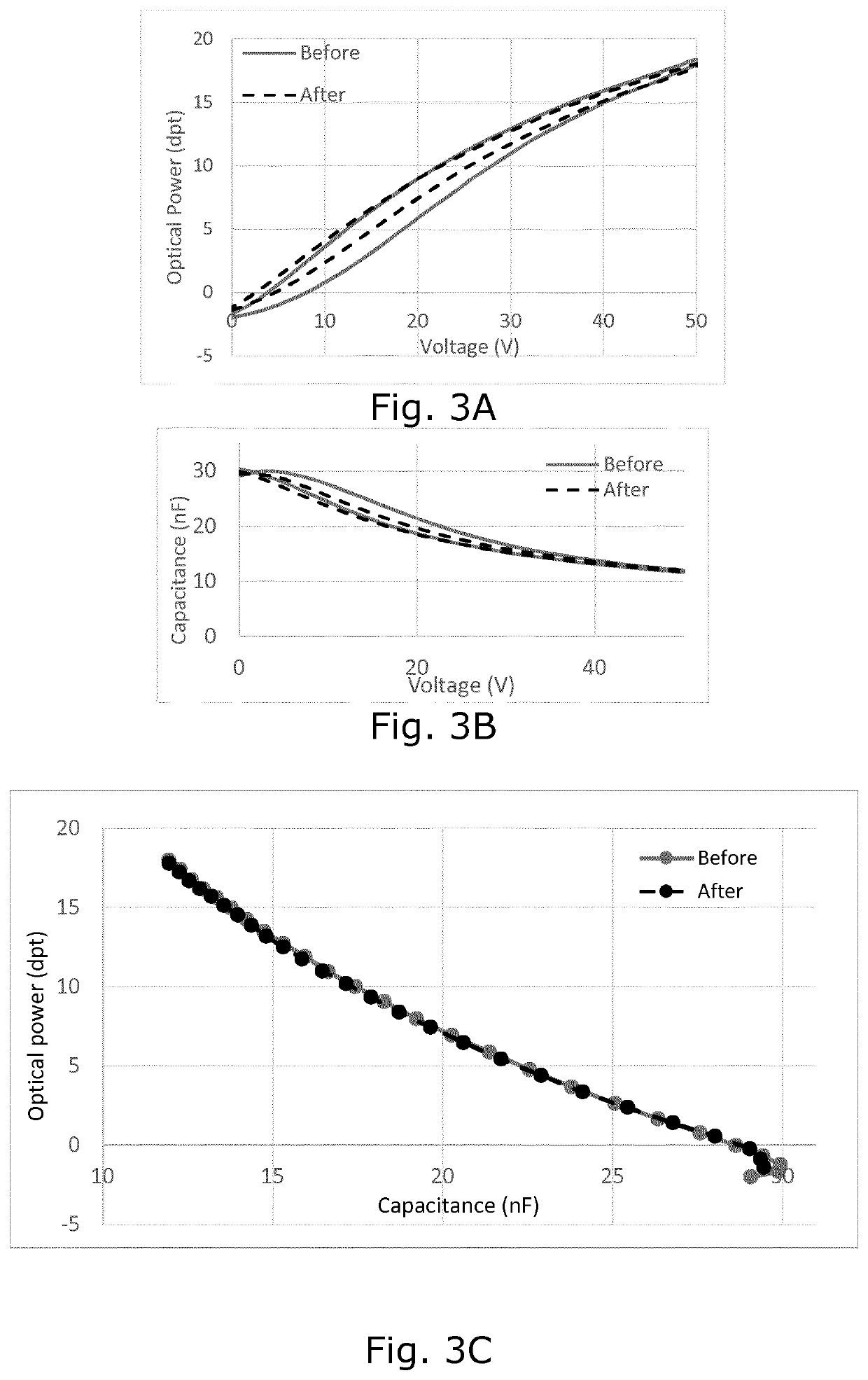
[0059]The adjustable focus lens assembly can for example be a deformable, non-fluid lens body sandwiched between an optical support and a transparent, flexible membrane to form a lens, with a PEA in the form of a film arranged on the flexible membrane to deform the flexible membrane to change the focus of the lens. The PEA of the lens assembly can then be connected to a piezo driver involving a processing unit connected to the piezo driver and holding software for controlling the piezo driver. Such adjustable lens assembly is described in e.g. WO 2008 / 035983. The various measurements described and shown are obtained from a setup on a laboratory bench, and in this setup the displacement measure is optical power measured in dioptre. Measurement of optical power, however, is not practical in normal use of the in...


PUM


Abstract

The invention relates to a method and an actuator system for determining and applying a voltage to a piezoelectric actuator (PEA) to achieve a given setpoint displacement. The method involves determining a relation dcal(V) between a PEA displacement measure (d) and voltage (V) and a relation ttcal(V) between transition time (tt) and voltage and combining the determined relations to calculate a relation d(tt) between the displacement measure and transition time during an initial calibration procedure. This relation is characteristic for the PEA, and by determining a new relation ttnew(V) after repeated biasing of the PEA, a compensated relation dc(V) can be calculated by substituting ttnew(V) in the calculated d(tt). The compensated relation dc(V) compensates for piezo creep effects due to the wear and can be used to determine the voltage to be applied directly, or be used in other compensation algorithms.

Description

FIELD OF THE INVENTION[0001]The invention relates to piezoelectric actuators (PEAs) and systems involving such PEAs, in particular the invention relates to compensating for non-linear phenomena in such systems.BACKGROUND OF THE INVENTION[0002]WO 2017 / 118732 describes an electronic circuit for controlling charging of a piezoelectric load arranged as an actuator in a deformable lens.[0003]Hysteresis and piezo creep are well known problems of PEAs. Piezo creep is the expression of the slow realignment of the crystal domains in a constant input voltage over time. If the operating voltage of a PZT is changed, after the voltage change is complete, the remnant polarization continues to change, manifesting itself in a slow creep. In closed loop setups—where the output is repeatedly checked against a desired value in a feedback loop to correct the voltage applied to the PEA—they can relatively easy be compensated for. The price, however, is time and power consumption which are disadvantageou...

Claims


Application Information

Patent Timeline
Patent Type & Authority Applications(United States)
IPC IPC(8): H02N2/06H04N5/225H04N5/232
CPCH02N2/062H04N5/23212H04N5/22521G02B7/08H10N30/802H04N23/52H04N23/67G03B2205/0061H04N23/54H04N23/57
Inventor HENRIKSEN, LARSSVORTDAL, TOREBARRON, EUANAZHAR, MUHAMMAD ASIF RAZATRAN, THI KIM TRINHTALLARON, NICOLASCRAEN, PIERRE
Owner POLIGHT ASA
Why Eureka
Try Eureka