Digital intelligent valve positioner

A valve positioner, intelligent technology, applied in the direction of valve details, valve devices, valve operation/release devices, etc., can solve the problems of only reset, waste of resources, large gas consumption, etc., to achieve power-off position protection and Reset, improve control accuracy, and save energy

Active Publication Date: 2019-06-18
深圳市新可优科技有限公司
View PDF6 Cites 0 Cited by
  • Summary
  • Abstract
  • Description
  • Claims
  • Application Information

AI Technical Summary

Problems solved by technology

[0003] At present, most of the valve positioners on the market are nozzle baffle type valve positioners. The principle is to convert the analog signal of the host computer into an air pressure signal, and the air pressure signal passes through the nozzle baffle, the complex transmission mechanism and the valve position feedback signal. It is connected with each other to achieve the purpose of adjustment. Its structure is complex. The principle is to rely on continuous injection of corresponding gas to maintain the valve position. When the gas source is interrupted, the purpose of maintaining the position cannot be achieved, and the gas consumption is also large.
[0004] The nozzle baffle type valve positioner needs to continuously consume compressed gas when it is working, and it can only be reset after the gas is cut off. The cost is high, and the position retention must be achieved by adding an additional solenoid valve group

Method used


Image

  • Digital intelligent valve positioner
  • Digital intelligent valve positioner
  • Digital intelligent valve positioner

Examples


Embodiment 1

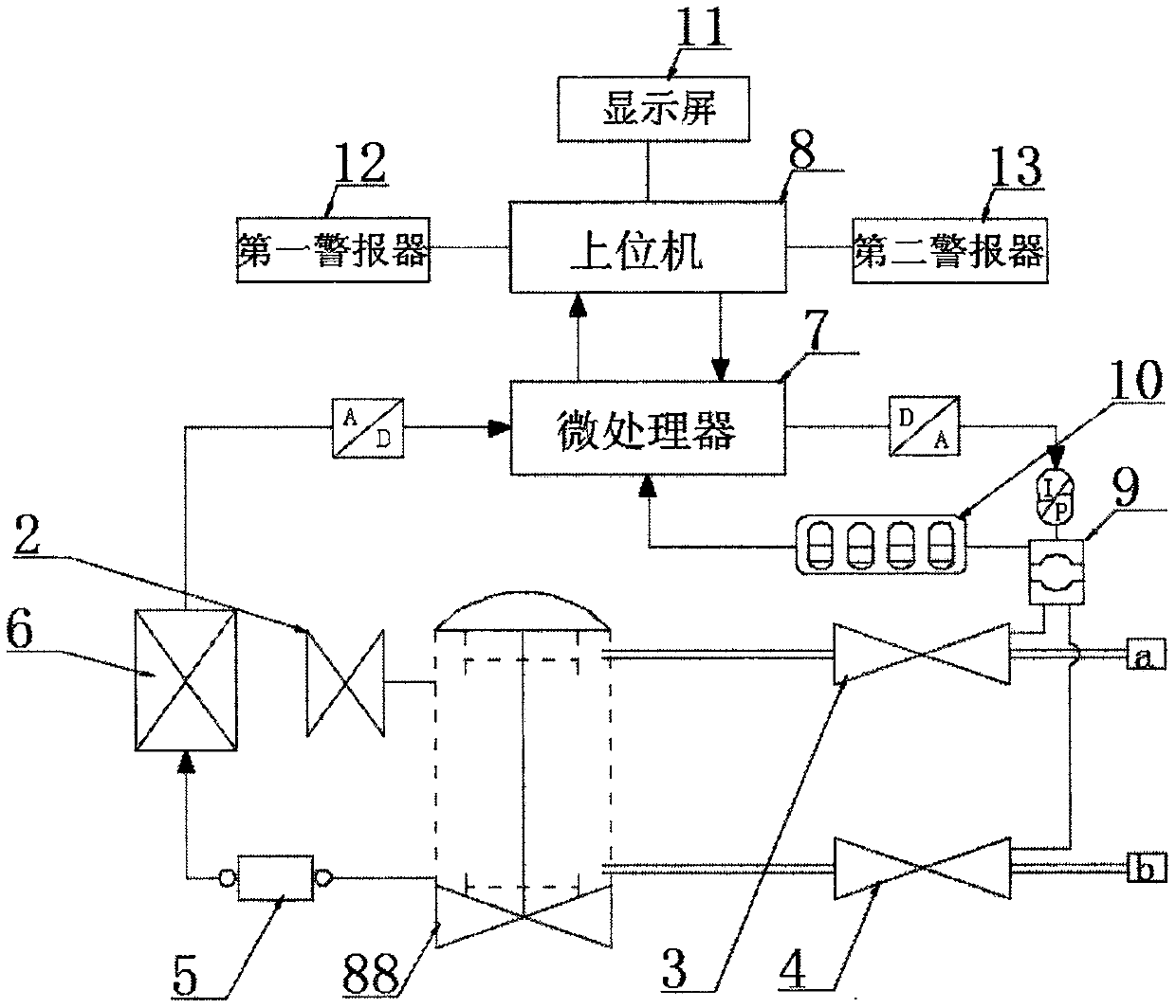
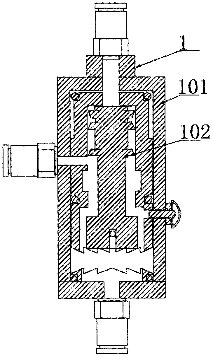
[0025] according to Figure 1-3 A digital intelligent valve positioner shown includes a pneumatic control valve 1, the pneumatic control valve 1, the pneumatic control valve 1 includes a cylinder body 101, and both ends of the cylinder body 101 are provided with mechanical limiters. position, the cylinder body 101 is slidingly connected with a valve stem 102, the top of the cylinder body 101 is provided with a first gas source inlet, the bottom of the cylinder body 101 is provided with a second gas source inlet, and one side of the cylinder body 101 An air source outlet is provided, the connection end of the pneumatic regulating valve 1 is provided with a retaining valve 2, a first piezoelectric valve 3 is provided on the side of the first air source inlet, and a first piezoelectric valve 3 is provided on the side of the second air source inlet. There is a second piezoelectric valve 4, a valve stem feedback mechanism 5 is provided at the gas source outlet of the pneumatic cont...

Embodiment 2

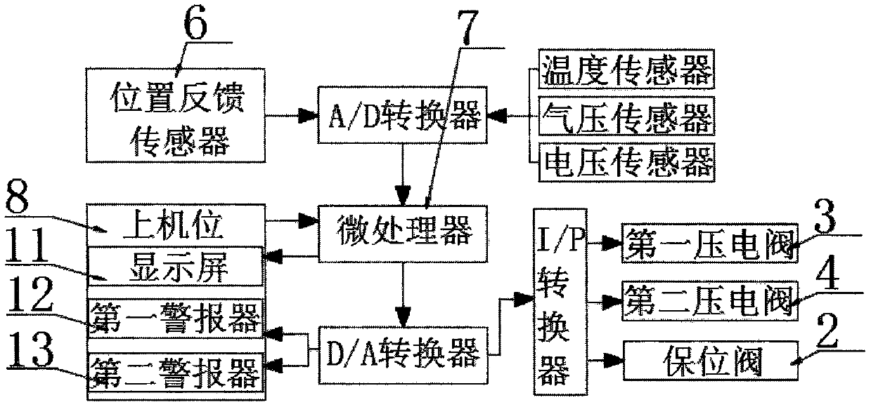
[0028] according to Figure 1-3 As shown in a digital intelligent valve positioner, the upper computer 8 includes a display screen 11, a first alarm 12 and a second alarm 13, and the display screen 11 is used to display the working parameters of each component and the valve The movement position of the rod 102, the first alarm 12 is used for the alarm of the jamming failure of the pneumatic control valve 1, the second alarm 13 is used for the alarm of the working failure of the pneumatic actuator 9, and the position feedback sensor 6 sets the valve stem The position signal is sent to the microprocessor 7 and compared with the input signal of the upper computer. When the data deviation is greater than the set value, the microprocessor 7 controls the first alarm 12 to alarm, prompting the pneumatic regulating valve 1 to block a fault, and the jamming The blocking position is displayed on the display screen 11 to realize valve blocking diagnosis;

[0029] Further, the host compu...


PUM


Abstract

The invention discloses a digital intelligent valve positioner, and particularly relates to the field of intelligent control of process industry. The digital intelligent valve positioner comprises a pneumatic regulating valve, the pneumatic regulating valve comprises a cylinder body, the two ends of the interior of the cylinder body are respectively provided with mechanical limits, the interior ofthe cylinder body is connected with a valve rod in a sliding mode, a first gas source inlet is formed in the top of the cylinder body, and a second gas source inlet is formed in the bottom of the cylinder body. According to the digital intelligent valve positioner, a first piezoelectric valve and a second piezoelectric valve are matched with a microprocessor to work, the CPU is respectively located at two mechanical limit memory zero positions and a 100% point position, the split signals are divided according to the preset precision grades, the number of the divided signals is memorized, automatic stroke positioning of the valve rods is realized, the digital signals are transmitted, the control precision is improved, the structure is simple, the maintenance is convenient, the retention ofthe valve rod is realized through a retaining valve, air consumption is not needed in addition to work, energy is saved, the power-off or air-cut can be selected for maintaining or resetting, energyis saved, and the environment is protected.

Description

technical field [0001] The invention relates to the field of intelligent control of process industry, more specifically, the invention relates to a digital intelligent valve positioner. Background technique [0002] The intelligent valve positioner, also known as the pneumatic valve positioner, is the main accessory of the control valve. It is usually used in conjunction with the pneumatic control valve. It receives the output signal of the regulator, and then controls the pneumatic control valve with its output signal area. When the control valve After the action, the displacement of the valve stem is fed back to the valve positioner through the mechanical device, and the valve position status is transmitted to the upper system through the electrical signal. [0003] At present, most of the valve positioners on the market are nozzle baffle type valve positioners. The principle is to convert the analog signal of the host computer into an air pressure signal, and the air pres...

Claims


Application Information

Patent Timeline
Patent Type & Authority Applications(China)
IPC IPC(8): F16K31/12F16K37/00
Inventor 曹锦
Owner 深圳市新可优科技有限公司
Why Eureka
Try Eureka