
Novel efficient centrifugal dehydrator

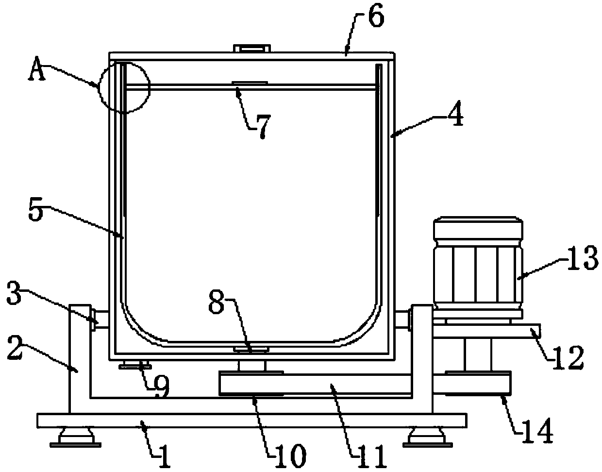
A centrifugal dehydrator, high-efficiency technology, applied in dryers, drying solid materials, drying solid materials without heating, etc., can solve the problems of reduced dehydration efficiency, slow drainage speed of dehydration holes, collision between cotton and cylinder wall, etc., to achieve Reasonable structural design, good drainage effect and simple operation

Inactive Publication Date: 2019-06-18
宜昌市雅丰医用敷料有限公司
View PDF0 Cites 2 Cited by
  • Summary
  • Abstract
  • Description
  • Claims
  • Application Information

AI Technical Summary

Problems solved by technology

[0002] Cosmetic cotton is generally a small piece of cotton about 5-6 cm long made of cotton. There are many uses for using cosmetic cotton. The main purpose is to remove makeup, because its texture is very soft and it is not easy to hurt the face when removing makeup. , and pouring toner on it is very comfortable to use, and it will also remove makeup very cleanly. Cotton cotton needs to be washed and bleached during processing, and then dehydrated. The existing dehydration device has a simple structure, and more dehydration holes are set on the dehydration device. The dehydration hole drains slowly, which reduces the dehydration efficiency. At the same time, the connection between the pressure plate and the dehydration cylinder during dehydration is smooth, and the cotton is prone to unstable pressing, which will cause the cotton to collide with the cylinder wall during dehydration. Abnormal noise

Method used


Image

  • Novel efficient centrifugal dehydrator
  • Novel efficient centrifugal dehydrator
  • Novel efficient centrifugal dehydrator

Examples


Embodiment Construction

[0015] The technical solutions of the present invention will be clearly and completely described below in conjunction with the accompanying drawings. In the description of the present invention, it should be noted that the terms "center", "upper", "lower", "left", "right", "vertical", "horizontal", "inner", "outer" etc. The indicated orientation or positional relationship is based on the orientation or positional relationship shown in the drawings, and is only for the convenience of describing the present invention and simplifying the description, rather than indicating or implying that the referred device or element must have a specific orientation, or in a specific orientation. construction and operation, therefore, should not be construed as limiting the invention. In addition, the terms "first", "second", and "third" are used for descriptive purposes only, and should not be construed as indicating or implying relative importance.

[0016] In the description of the present...


PUM


Abstract

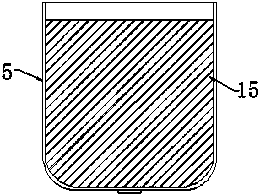
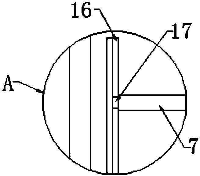
The invention discloses a novel efficient centrifugal dehydrator and is used in the field of cotton product processing. The novel efficient centrifugal dehydrator comprises a base and a box body; a mounting frame is fixedly mounted on the surface of the top of the base; mounting columns are fixedly mounted on the inner walls of the two sides of the mounting frame; one side of the mounting frame isfixedly connected with a motor frame; a rotating motor is mounted at the top of the motor frame; and the output end of the rotating motor is connected with a driving wheel. The novel efficient centrifugal dehydrator is reasonable in structural design and easy to operate, with the adoption of a centrifugal barrel, drainage oblique strips are arranged on the surface and at the bottom of the centrifugal barrel, so that moisture in cotton is rapidly separated and removed through the centrifugal effect when the centrifugal barrel rotates; compared with relatively traditional drainage holes, the drainage oblique strips arranged on the surface and at the bottom of the centrifugal barrel are better in the drainage effect; and with the adoption of a pressure plate, the pressure plate is in slidingconnection with a sliding groove in the centrifugal barrel through a sliding block, and the cotton in the centrifugal barrel is effectively compacted, so that abnormal sounds generated due to the fact that the cotton is not compacted and collides with the barrel wall during dehydration are avoided.

Description

technical field [0001] The invention relates to the field of cotton product processing equipment, in particular to a novel high-efficiency centrifugal dehydrator. Background technique [0002] Cosmetic cotton is generally a small piece of cotton about 5-6 cm long made of cotton. There are many uses for using cosmetic cotton. The main purpose is to remove makeup, because its texture is very soft and it is not easy to hurt the face when removing makeup. , and pouring toner on it is very comfortable to use, and it will also remove makeup very cleanly. Cotton cotton needs to be washed and bleached during processing, and then dehydrated. The existing dehydration device has a simple structure, and more dehydration holes are set on the dehydration device. The dehydration hole drains slowly, which reduces the dehydration efficiency. At the same time, the connection between the pressure plate and the dehydration cylinder during dehydration is smooth, and the cotton is prone to unstab...

Claims


Application Information

Patent Timeline
IPC IPC(8): F26B5/08F26B25/08F26B25/00
Inventor 蔡大军
Owner 宜昌市雅丰医用敷料有限公司
Learn More