

Inner cavity diameter measuring device of hub
A technology of diameter measurement and inner cavity, which is applied in the direction of mechanical diameter measurement, etc., can solve the problem that there is no way to measure the diameter D of the wheel position, etc., and achieve the effect of easy operation, accurate measurement and strong versatility
- Summary
- Abstract
- Description
- Claims
- Application Information
AI Technical Summary
Problems solved by technology
Method used
Image

Examples
Embodiment 1
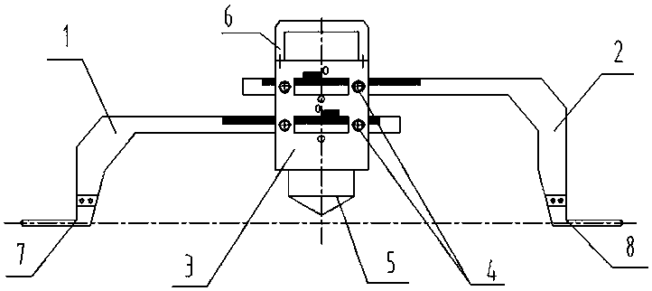
[0024] The following is attached with the manual Figure 1-4 Embodiment 1 of the present invention is illustrated:
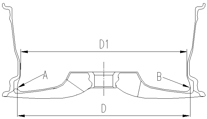
[0025] according to figure 2 The device for measuring the diameter of the inner cavity of a hub includes a left floating scale 1 , a right floating scale 2 , a measuring tool body 3 , a positioning component, a fastening component, a measuring tool handle 6 , a left contact 7 , and a right contact 8 . The measuring tool main body 3 is provided with upper and lower ruler grooves which run through the measuring tool body in parallel up and down. The middle part of the upper ruler groove is provided with a section of upper reading window, and the middle part of the lower ruler groove is also provided with a section of lower reading window. On 3, an upper scale is provided along the upper edge of the upper reading window, and a lower scale is provided on the measuring tool main body 3 along the upper edge of the lower reading window; The lower scales are all 10 s...
Embodiment 2
[0034] The difference between embodiment 2 and embodiment 1 is that the upper and lower positions of the left and right floating scales are different. Specifically in embodiment 2, the 0 scale line of the upper scale is on the far left, the 0 scale line of the lower scale is on the far right, the right floating scale is inserted into the lower ruler groove to slide, and the left wandering scale is inserted into the upper ruler groove to slide; The fastening part is arranged on the main body of the measuring tool, and is used for fixing the left floating scale and the right floating scale in the upper ruler groove and the lower ruler groove respectively when reading. In embodiment 2, only the up and down positions of the left and right swimming scales are different, and the rest of the components and their connecting structures and reading methods are the same as those in embodiment 1.
[0035] Implementation: 3:
Embodiment 3
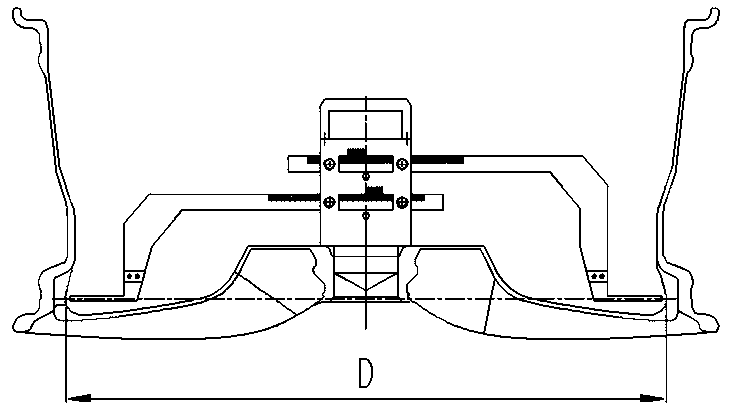
[0036] The difference between Embodiment 3 and Embodiment 1 lies in that the corresponding relationship between the upper scale and the lower scale is set differently, so that there is a difference in the algorithm of the inner diameter D of the wheel. In Example 3, such as Figure 5 As shown, the scale line positions of the upper scale and the lower scale on the main body of the measuring tool 3 are in one-to-one correspondence, and the upper and lower scale lines of the one-to-one correspondence are on a vertical line; The reading method of 2 is the same as that in embodiment 1, but the inner diameter of the wheel D=the reading of the right traveling scale 2+the reading of the left traveling scale 1+the length of the upper scale or the lower scale, thereby measuring the diameter of the inner cavity of the wheel hub. The rest of the components and their connections are the same as those in Embodiment 1.
[0037] It can be seen that the present invention provides a wheel hub ...
PUM
 Abstract
Description
Claims
Application Information