Steel wire pre-forming measuring rod and application method thereof

An application method and technology of preformed rods, applied in the direction of measuring device, mechanical diameter measurement, mechanical gap measurement, etc., can solve the problems of cumbersome operation, complicated parameter control, inconvenient application, etc., and achieve the effect of high measurement accuracy

Active Publication Date: 2020-02-07
中金液压胶管股份有限公司
View PDF4 Cites 2 Cited by
  • Summary
  • Abstract
  • Description
  • Claims
  • Application Information

AI Technical Summary

Problems solved by technology

The steel wire reinforcement layer is located between the inner rubber layer and the outer rubber layer in the form of spiral wrapping. During the production process, it is necessary to select a material steel wire with a spiral shape and suitable screw diameter and pitch for stretch coating. If the selected material The steel wire is wrong, and the steel wire reinforced layer produced by it is difficult to ensure that the screw diameter and pitch meet the standards at the same time. When producing a steel wire reinforced layer, the selection of steel wire needs to go through many experiments and measurements before determining the suitable material. Screw diameter and pitch, while in the prior art, the parameter control to the preforming operation of steel wire is comparatively complicated; And in each measurement, the screw diameter and pitch of steel wire are all carried out separately, and its operation is comparatively loaded down with trivial details, and application is inconvenient; In addition, there is no special device for stretching the helical steel wire in the prior art

Method used


Image

  • Steel wire pre-forming measuring rod and application method thereof
  • Steel wire pre-forming measuring rod and application method thereof
  • Steel wire pre-forming measuring rod and application method thereof

Examples


Embodiment 1

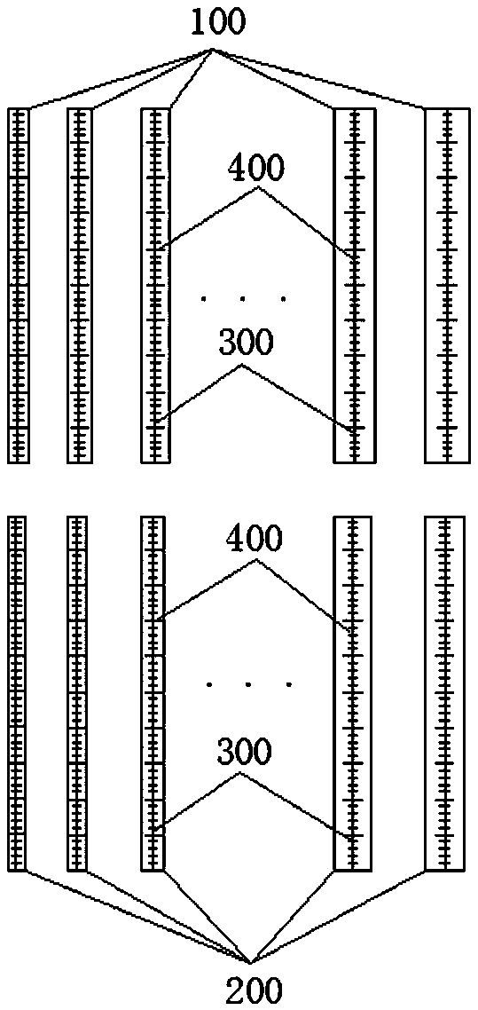
[0036] Such as figure 1 A steel wire preformed measuring rod shown includes several preformed rods 100 of different diameters and several standard measuring rods 200 of different diameters. Both the preformed rod and the standard measuring rod are marked with a straight line 300 along their length direction, and the straight line 300 is marked with a length scale 400; the materials of the preformed rod 100 and the standard measuring rod 200 are both nylon. Nylon has strong properties such as wear resistance, and the preformed rod 100 and standard measuring rod 200 made of it have good structural stability and can prevent being scratched and worn by steel wires.

[0037] For the 4SP-10 rubber hose (which includes four layers of steel wire reinforcement, and the diameter and pitch of each layer of steel wire reinforcement are known), now use the above steel wire preformed measuring rod to select materials that can be directly used to prepare the steel wire reinforcement steel w...


PUM

PropertyMeasurementUnit
distanceaaaaaaaaaa
distanceaaaaaaaaaa
distanceaaaaaaaaaa

Abstract

The invention discloses a steel wire pre-forming measuring rod and an application method thereof, and belongs to the technical field of high-pressure steel wire winding rubber tube processing. The steel wire pre-forming measuring rod comprises a plurality of pre-forming rods and standard measuring rods, which are of different diameters, wherein length graduated scales are marked on the pre-formingrods and the standard measuring rods in a length direction; during application, the standard measuring rods of the same diameter and the pre-forming rods of relatively great diameters are selected according to a corresponding steel wire reinforcing layer, steel wires are wound on the pre-forming rods to manufacture pre-formed steel wires, the pre-formed steel wires sleeve the standard measuring rods so as to stretch by a stretching device until the steel wires are completely attached to the surfaces of the standard measuring rods, and screw pitches of the stretched steel wires can be directlyobtained through the length graduated scales, and the screw pitches are judged to whether reach standards or not. Pre-forming and measuring operation of the steel wires are relatively simple; the stretching device adopted during application can conveniently dismount the standard measuring rods, and can stably clamp the pre-formed steel wires, so that stretching control is simple, and stretching of the pre-formed steel wires further can be timely stopped.

Description

technical field [0001] The invention relates to the technical field of high-pressure steel wire wound rubber hose processing, in particular to a steel wire preformed measuring rod and an application method thereof. Background technique [0002] The structure of the high-pressure steel wire wound rubber hose is mainly composed of an inner rubber layer, a middle rubber layer, four or more layers of alternately wound steel wire reinforcement layers and an outer rubber layer. The inner rubber layer has the function of making the conveying medium withstand pressure and protecting the steel wire from erosion. , The outer rubber layer protects the steel wire from damage, and the steel wire reinforcement layer (ф0.3-2.0) is a skeleton material, which acts as a reinforcement. The steel wire reinforcement layer is located between the inner rubber layer and the outer rubber layer in the form of spiral wrapping. During the production process, it is necessary to select a material steel w...

Claims


Application Information

Patent Timeline
Patent Type & Authority Applications(China)
IPC IPC(8): B21F17/00B21C51/00G01B5/02G01B5/08G01B5/16G01V8/10
CPCB21C51/00B21F17/00G01B5/02G01B5/08G01B5/16G01V8/10
Inventor 褚福金刘霞曹锐田成
Owner 中金液压胶管股份有限公司
Why Eureka
Try Eureka