Urban rainwater pipeline drainage intelligent monitoring device
An intelligent monitoring and pipeline technology, applied in measurement devices, water supply devices, waterway systems, etc., can solve problems such as the increase of the stagnant water area and the inability of the staff to monitor the drainage pipelines all the time.
- Summary
- Abstract
- Description
- Claims
- Application Information
AI Technical Summary
Problems solved by technology
Method used
Image


Examples
Embodiment 1
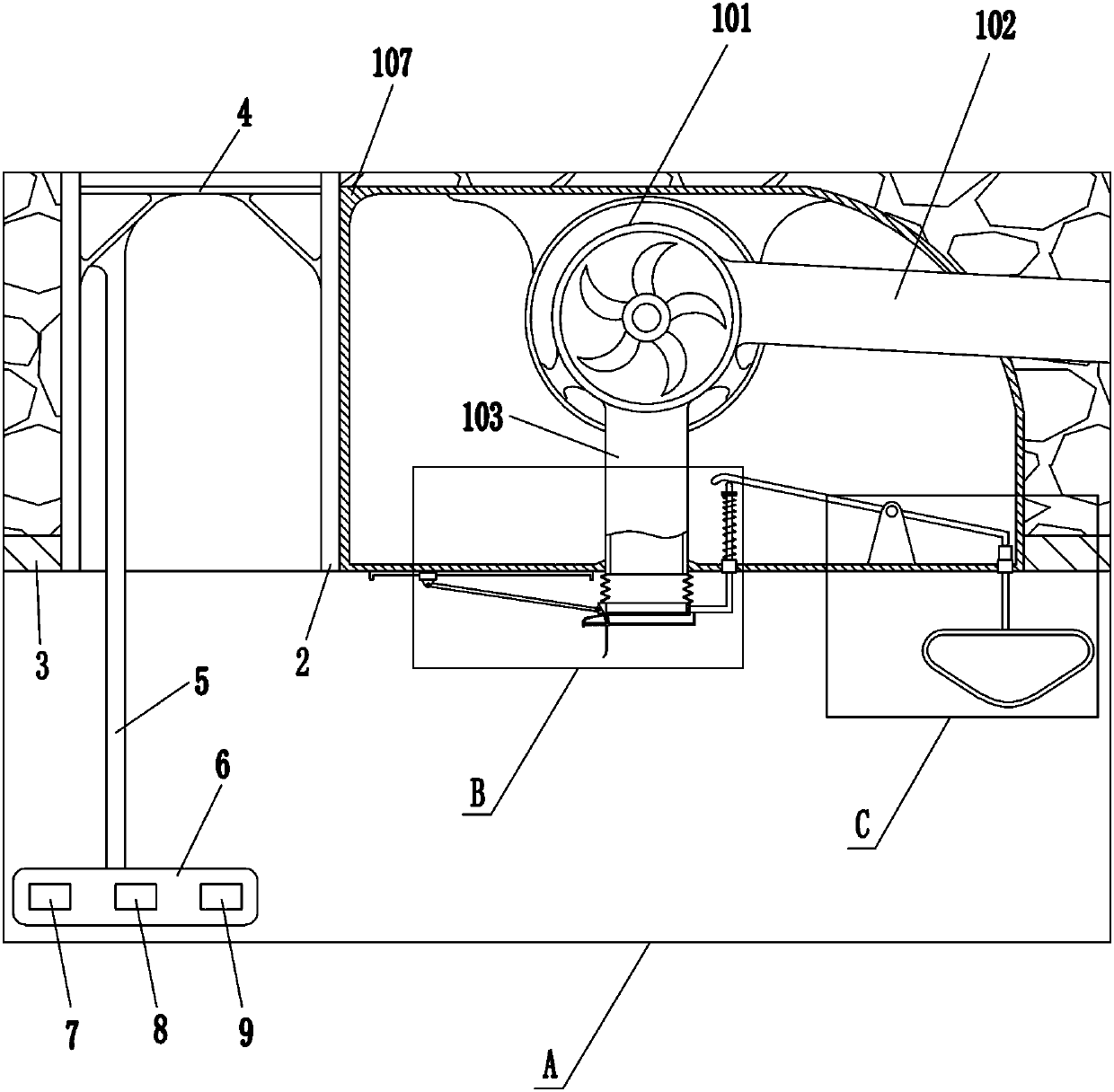
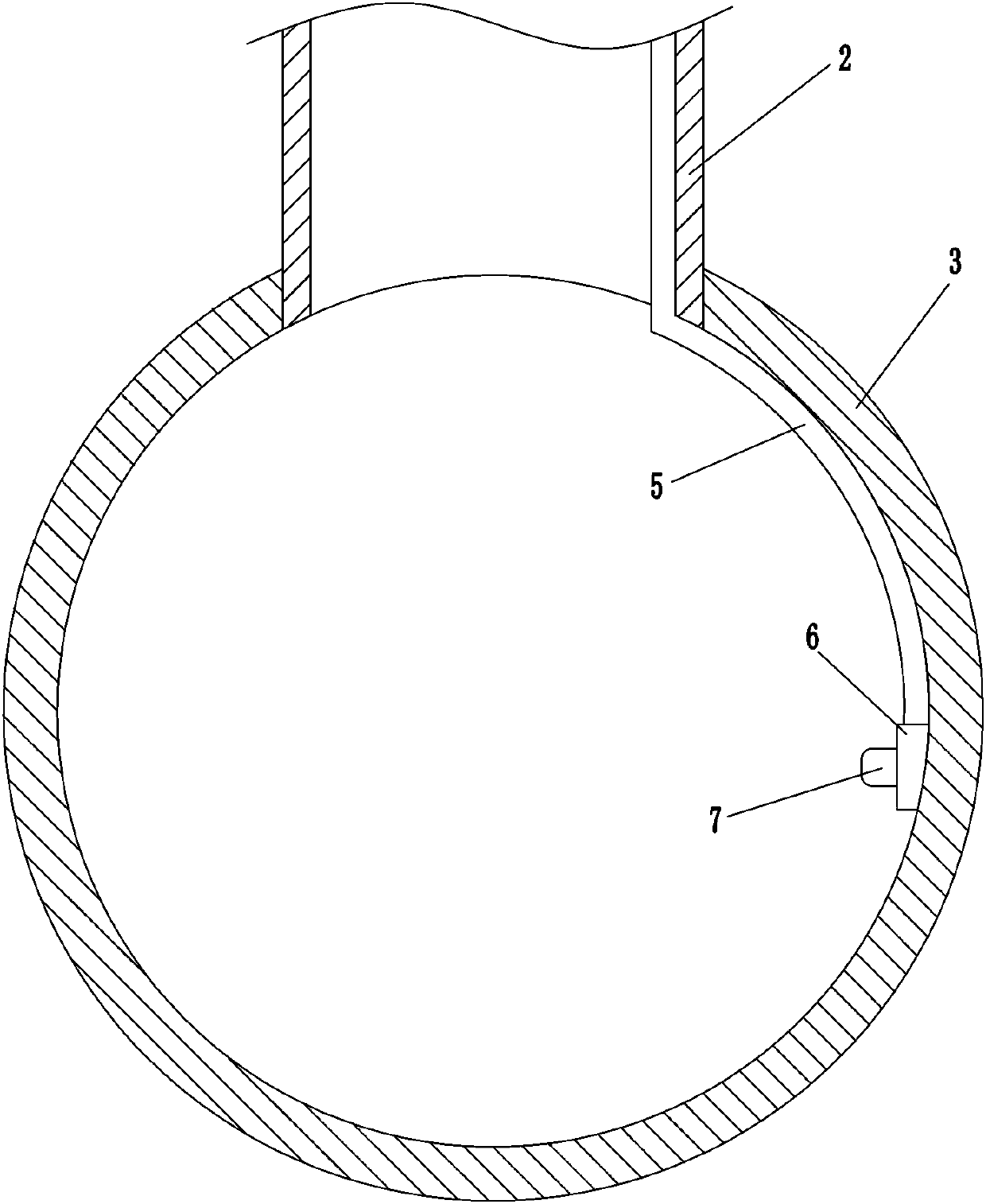
[0024] A kind of urban rainwater pipeline drainage intelligent monitoring device, such as Figure 1-10 As shown, it includes a control room 1, a support frame 4, a fixed rod 5, a mounting plate 6, a first acoustic Doppler flow meter 7, a second acoustic Doppler flow meter 8, and a third acoustic Doppler flow meter 9 and the drainage device 10, the control room 1 includes a GPRS wireless remote control switch circuit breaker, a power supply module, a control module, a first indicator light, a second indicator light, a third indicator light, a fourth indicator light and an LCD display screen, three Two ultrasonic Doppler flowmeter hosts and three storage batteries are installed in the middle of the inner wall of the downpipe 2. The three storage batteries are respectively connected to the three ultrasonic Doppler flowmeter hosts by lines, and the three ultrasonic Doppler flowmeter hosts are all connected to the background server. Through the GPRS wireless connection, the storage...
Embodiment 2
[0026] A kind of urban rainwater pipeline drainage intelligent monitoring device, such as Figure 1-10As shown, it includes a control room 1, a support frame 4, a fixed rod 5, a mounting plate 6, a first acoustic Doppler flow meter 7, a second acoustic Doppler flow meter 8, and a third acoustic Doppler flow meter 9 and the drainage device 10, the control room 1 includes a GPRS wireless remote control switch circuit breaker, a power module, a control module, a first indicator light, a second indicator light, a third indicator light, a fourth indicator light and an LCD display screen, three Two ultrasonic Doppler flowmeter hosts and three storage batteries are installed in the middle of the inner wall of the downpipe 2. The three storage batteries are connected to the three ultrasonic Doppler flowmeter hosts respectively, and the three ultrasonic Doppler flowmeter hosts are all connected to the background server. Through the GPRS wireless connection, the storage battery can supp...
Embodiment 3
[0029] A kind of urban rainwater pipeline drainage intelligent monitoring device, such as Figure 1-10 As shown, it includes a control room 1, a support frame 4, a fixed rod 5, a mounting plate 6, a first acoustic Doppler flow meter 7, a second acoustic Doppler flow meter 8, and a third acoustic Doppler flow meter 9 and the drainage device 10, the control room 1 includes a GPRS wireless remote control switch circuit breaker, a power module, a control module, a first indicator light, a second indicator light, a third indicator light, a fourth indicator light and an LCD display screen, three Two ultrasonic Doppler flowmeter hosts and three storage batteries are installed in the middle of the inner wall of the downpipe 2. The three storage batteries are connected to the three ultrasonic Doppler flowmeter hosts respectively, and the three ultrasonic Doppler flowmeter hosts are all connected to the background server. Through the GPRS wireless connection, the storage battery can sup...
PUM
 Abstract
Description
Claims
Application Information
PatSnap Eureka turns technology decisions into work you can execute. Powered by our Innovation Knowledge Graph, it runs expert workflows across engineering, life sciences, materials and intellectual property. Get your review-ready output in minutes.


