A Path Tracking Method for Autonomous Underwater Vehicle Based on Heading Smoothing Technology

An underwater robot, path tracking technology, applied in instruments, adaptive control, control/regulation systems, etc., can solve problems such as low path tracking accuracy

Active Publication Date: 2021-10-29
HARBIN ENG UNIV
View PDF15 Cites 0 Cited by
  • Summary
  • Abstract
  • Description
  • Claims
  • Application Information

AI Technical Summary

Problems solved by technology

[0005] The purpose of the present invention is to solve the problem of low path tracking accuracy when the heading crosses the -π / π discontinuity point in the existing AUV path tracking control, and propose an autonomous underwater robot path based on heading smoothing technology tracking method

Method used


Image

  • A Path Tracking Method for Autonomous Underwater Vehicle Based on Heading Smoothing Technology
  • A Path Tracking Method for Autonomous Underwater Vehicle Based on Heading Smoothing Technology
  • A Path Tracking Method for Autonomous Underwater Vehicle Based on Heading Smoothing Technology

Examples


specific Embodiment approach 1

[0024] Specific implementation mode 1: In this implementation mode, a specific process of an autonomous underwater robot path tracking method based on heading smoothing technology is as follows:

[0025] Step 1. Measure the state measurement value of the AUV at the initial moment, and set the expected path p(σ) of the AUV;

[0026] Step 2, measuring the state measurement value of the current AUV, and obtaining the path tracking error of the AUV according to the state measurement value of the current AUV and the expected path p(σ) of the AUV;

[0027] Path tracking error e p (t) contains the distance between the current position of the AUV and the position of the desired point at the current moment (x(σ(t)), y(σ(t))), the current heading angle and the desired heading angle ψ(σ(t) )) difference;

[0028] Step 3, optimize the difference between the current heading angle obtained in step 2 and the desired heading angle ψ(σ(t)), and obtain the reference heading input to the contr...

specific Embodiment approach 2

[0032] Specific embodiment two: the difference between this embodiment and specific embodiment one is that the state measurement value of the current AUV is measured in the second step, and the path of the AUV is obtained according to the current state measurement value of the AUV and the expected path p(σ) of the AUV Tracking error; the specific process is:

[0033] Set the mathematical model of AUV horizontal plane motion:

[0034]

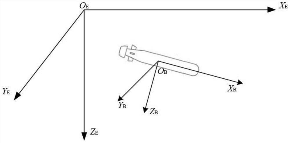
[0035] where η=[x′ y ψ] T are the coordinates and attitude angle in the geodetic coordinate system, x′, y are the position of the AUV in the geodetic coordinate system, ψ is the heading of the AUV in the geodetic coordinate system, and the superscript T means transpose, is the relationship between the earth coordinate system and the satellite coordinate system, R(ψ) is the horizontal plane coordinate transformation matrix; M=M RB +M A is the inertia matrix; M RB is the rigid body inertial matrix, M A is the additional mass matrix, v=[...

specific Embodiment approach 3

[0058] Specific embodiment three: the difference between this embodiment and specific embodiment one or two is that in the step three, the difference between the current heading angle obtained in step two and the desired heading angle ψ(σ(t)) is optimized , to get the reference heading input to the controller; the specific process is:

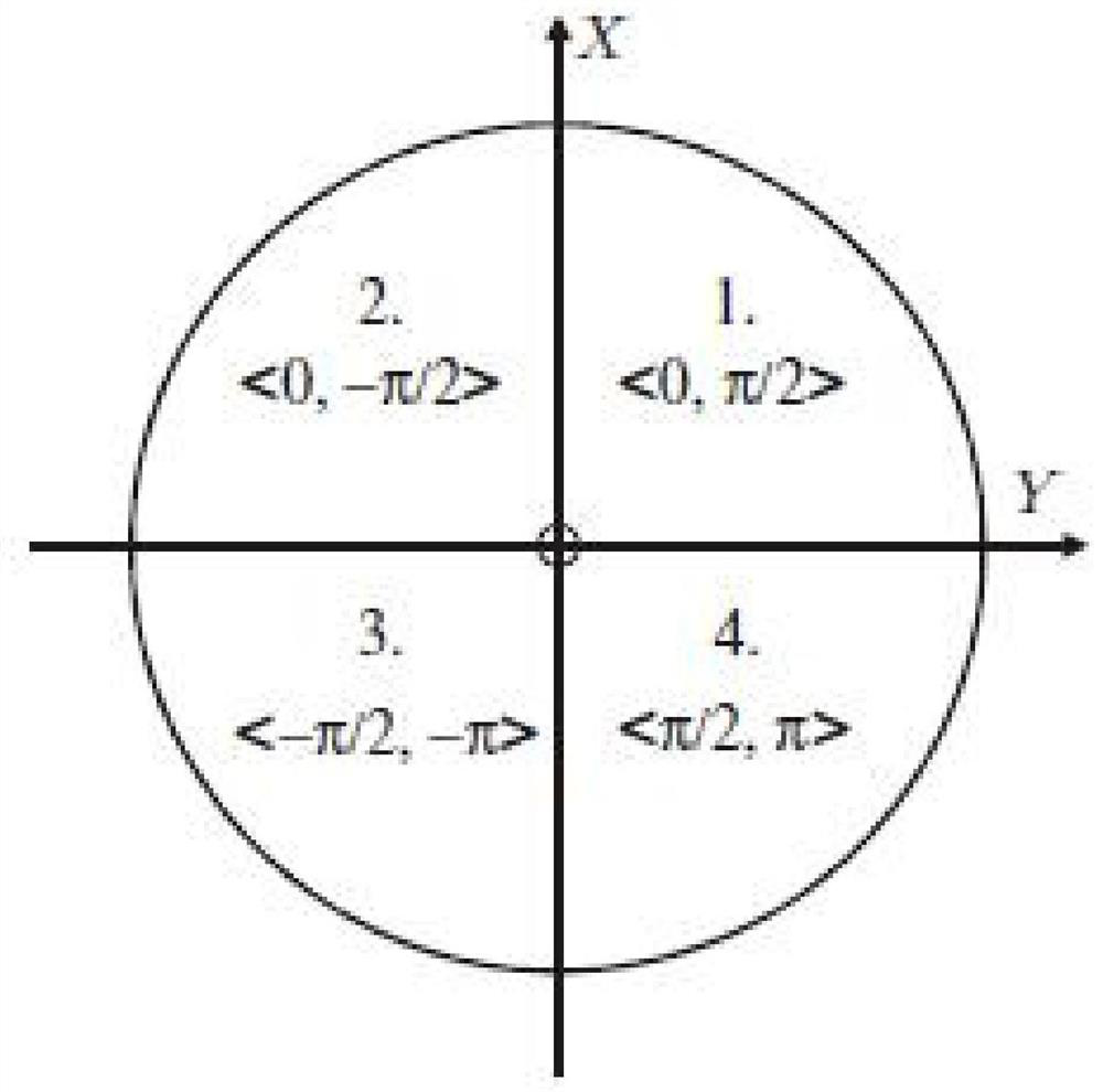
[0059] Because the difference between the current heading and the desired heading angle ψ(σ(t)) has a (-π,π] discontinuity point, causing the AUV to spin, so it is optimized;

[0060] Heading smoothing algorithm:

[0061] Although formula (6) gives the calculation formula of the expected angle of the reference point, the domain of the atan2 function is (-π, π], which will lead to discontinuity at the junction point of -π / π, which is very important for the path tracking problem It is very unfavorable, because it will cause the dynamic inconsistency between the reference heading and the AUV heading. When the AUV is tracking the path, there must ...


PUM


Abstract

A path tracking method for an autonomous underwater robot based on heading smoothing technology, and the invention relates to a path tracking method for an autonomous underwater robot. The purpose of the present invention is to solve the problem of low path tracking accuracy when the heading crosses the -π / π discontinuity point in the existing AUV path tracking control. The process is: 1. Measure the state measurement value of the AUV at the initial moment, and set the expected path of the AUV; 2. Obtain the path tracking error of the AUV; 3. Obtain the optimized path tracking error; 4. Converge the optimized path tracking error. Obtain the control input of the AUV, which includes the torque and force to control the AUV; 5. Determine whether the AUV has completed the tracking path. If it has completed the tracking path, obtain the control input of the AUV; if it has not completed the tracking path, execute the second step again. to five until the AUV completes the tracking path. The invention is used in the field of autonomous underwater robot path tracking.

Description

technical field [0001] The invention relates to a path tracking method for an autonomous underwater robot. Background technique [0002] In recent decades, with the rapid development of my country's economic and technological strength, the status of the ocean in the national strategy has also been significantly improved. Autonomous underwater vehicle (AUV) has attracted the attention of countries all over the world because of its ability to significantly reduce the risk and operating time of underwater operations. At present, many AUVs have been successfully applied to tasks such as subsea oil pipeline inspection and subsea hydrological inspection. Such applications have made the research on AUV an active field in system science and robotics. [1] (Cabezas J M, Pastor E, Camacho LM, et al. I-AUV Mechatronics Integration for the TRIDENT FP7 Project [J]. IEEE / ASME Transactions on Mechatronics, 2015, 20(5): 2583-2592.). [0003] When AUVs actually perform tasks, path tracking ...

Claims


Application Information

Patent Timeline
Patent Type & Authority Patents(China)
IPC IPC(8): G05B13/04
Inventor 万磊孙延超张靖宇秦洪德杜雨桐李晓佳李骋鹏
Owner HARBIN ENG UNIV
Why Eureka
Try Eureka