Breathable pressure release valve applied to power battery pack

A power battery pack and vent valve technology, applied in electrical components, battery pack components, circuits, etc., can solve the problems of poor consistency of blasting pressure, affecting sealing reliability, and small pressure relief diameter, achieving good versatility, The effect of reducing air convection and low pressure relief opening pressure

Active Publication Date: 2019-06-18
JIANGLING MOTORS
View PDF5 Cites 8 Cited by
  • Summary
  • Abstract
  • Description
  • Claims
  • Application Information

AI Technical Summary

Problems solved by technology

[0003] At present, spring blasting type venting pressure relief valves or thimble bursting type venting pressure relief valves are often used on battery packs. The blasting pressure of the thimble type bursting valves is relatively high, and the bursting pressure consistency is poor. A large amount of oxygen entering the box to participate in the reaction will cause the battery to burn again; the spring-opening blast valve has the disadvantages of small pressure relief path and foreign matter entering, which affects the sealing reliability; considering the lightweight design of the battery system, the battery box cover is mostly thin The wall is made of composite materials, and the box cover is difficult to withstand a pressure exceeding 10kPa. The above two kinds of ventilating pressure relief valves are difficult to ensure that the pressure in the box is less than 10kPa during the process of thermal runaway of the battery cell; a new type of breathable, ventilating and rapid pressure relief function is required. valve to ensure the safety of the power battery system

Method used


Image

  • Breathable pressure release valve applied to power battery pack
  • Breathable pressure release valve applied to power battery pack
  • Breathable pressure release valve applied to power battery pack

Examples


Embodiment Construction

[0037] The present invention will be further explained below in conjunction with the drawings and embodiments:

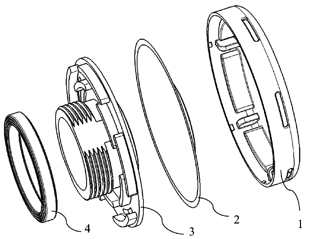
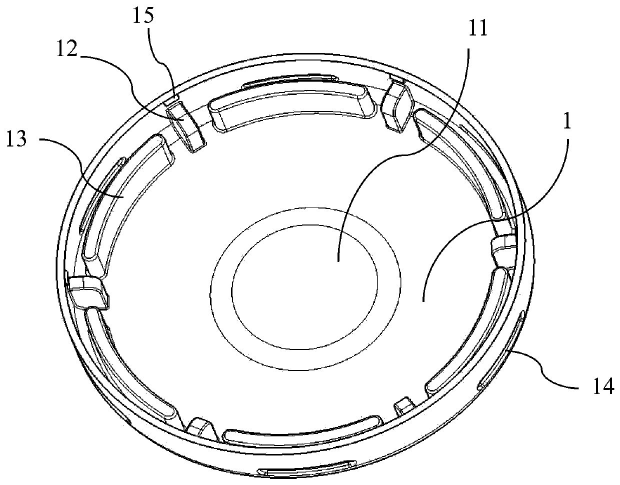
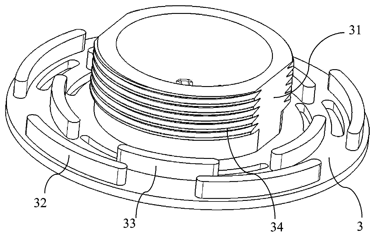
[0038] See Figure 1-13 .

[0039] In the description of the embodiments of the present invention, it is necessary to understand that the terms "upper", "lower", "inner", "outer" and so on indicate that the positional relationship is based on the positional relationship shown in the drawings, which is only for convenience of describing the present invention and is not a requirement. The present invention must be constructed in a specific positional relationship, so it should not be understood as a limitation to the present invention.

[0040] In the description of the present invention, the term "installation" should be understood in a broad sense. It can be a fixed connection or a detachable connection, which can be directly connected or indirectly connected through an intermediary; those skilled in the art can understand the above according to specific circumstances. T...


PUM


Abstract

The invention relates to the field of new energy automobiles, in particular to a breathable pressure release valve applied to a power battery pack. The breathable pressure release valve comprises a breathable valve protective cover, a breathable film and a breathable valve base; the breathable film is arranged between the breathable valve protective cover and the breathable valve base in a sleeving mode; a cavity structure with an opening is formed in the lower portion of a breathable valve protective cover main body; the inner edge of the cavity of the breathable valve protective cover is provided with a clamping structure used for clamping the breathable valve base; the outer edge of the breathable valve base is attached to the inner wall of the breathable valve protective cover; and a plurality of through vent holes are formed in the side walls of the breathable valve protective cover between the breathable valve protective cover and the breathable valve base in a point spacing mode. The breathable pressure release valve is convenient and rapid to mount; the breathable pressure release valve is mounted in a battery box shell with an opening position; the mounting can be completed by mounting a fastening piece in a box body; and the mounting process is short in time.

Description

Technical field [0001] The invention relates to the field of new energy vehicles, in particular to a ventilating pressure relief valve applied to a power battery pack. Background technique [0002] The power battery pack installed on the bottom of the vehicle needs to reach the IP67 protection level. Due to the heating of the battery cell during the charging and discharging process and the change of the external environment of the vehicle, it is necessary to realize the gas breathing inside and outside the box to ensure the pressure balance inside and outside the box. So as to ensure the reliability of the sealing structure; in addition, the battery pack must be able to achieve rapid exhaust and pressure relief under extreme conditions such as thermal runaway of the battery cell. [0003] Currently, spring blasting type venting pressure relief valves or thimble blasting type venting pressure relief valves are mostly used on battery packs. The blasting pressure of thimble blasting v...

Claims


Application Information

Patent Timeline
Patent Type & Authority Applications(China)
IPC IPC(8): H01M2/12
CPCY02E60/10
Inventor 林金源董冰金小娇吴志斌
Owner JIANGLING MOTORS
Why Eureka
Try Eureka