
Test device for conduit burst pressure under static conditions and working method thereof

A burst pressure, testing device technology, applied in the direction of measuring device, using stable tension/pressure test material strength, instrument, etc., can solve the problem of leakage of test catheter, large difference in catheter size and injection pressure, and inability to obtain accurate test results and other issues to achieve the effect of high safety and high reference value

Pending Publication Date: 2019-06-21
山东省医疗器械产品质量检验中心
View PDF0 Cites 1 Cited by
  • Summary
  • Abstract
  • Description
  • Claims
  • Application Information

AI Technical Summary

Problems solved by technology

[0006] The relevant standard involving the quality and performance testing of intravascular power injection catheters is YY0285.1-2017 "Intravascular Catheters Disposable Sterile Catheters Part 1: General Requirements", but this standard only gives basic research methods and simple The schematic diagram of the test device, and there are many kinds of power injection catheters in clinical applications, and the size of the catheter and the injection pressure are quite different. Further research on the specific test plan and test device is needed
[0007] Appendix F of the medical device industry standard YY0285.1-2017 provides a normative overview of the test requirements for burst pressure testing under static conditions. During the test, the test fluid needs to be supplied to the test catheter at a stable rate. Stable flow rate output is likely to cause leakage or bursting of the test tube due to pressure fluctuations caused by flow rate fluctuations, resulting in inability to obtain accurate test results

Method used


Image

  • Test device for conduit burst pressure under static conditions and working method thereof
  • Test device for conduit burst pressure under static conditions and working method thereof
  • Test device for conduit burst pressure under static conditions and working method thereof

Examples


Embodiment Construction

[0058] The technical solutions of the present invention will be clearly and completely described below in conjunction with the accompanying drawings. Apparently, the described embodiments are some of the embodiments of the present invention, but not all of them.

[0059] The components of the embodiments of the invention generally described and shown in the figures herein may be arranged and designed in a variety of different configurations. Accordingly, the following detailed description of the embodiments of the invention provided in the accompanying drawings is not intended to limit the scope of the claimed invention, but merely represents selected embodiments of the invention.

[0060] Based on the embodiments of the present invention, all other embodiments obtained by persons of ordinary skill in the art without making creative efforts belong to the protection scope of the present invention.

[0061] In the description of the present invention, it should be noted that the...


PUM


Abstract

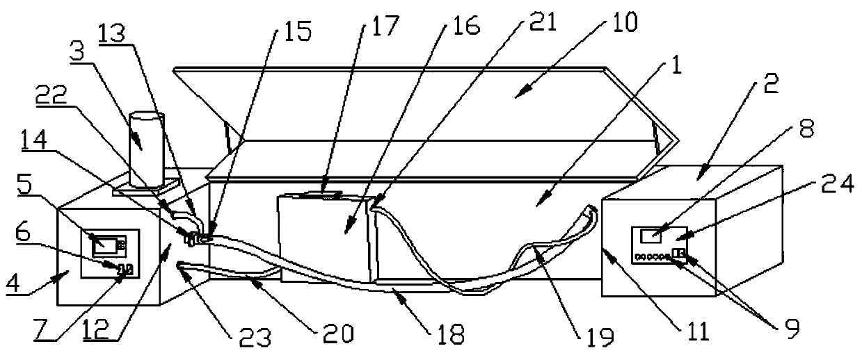
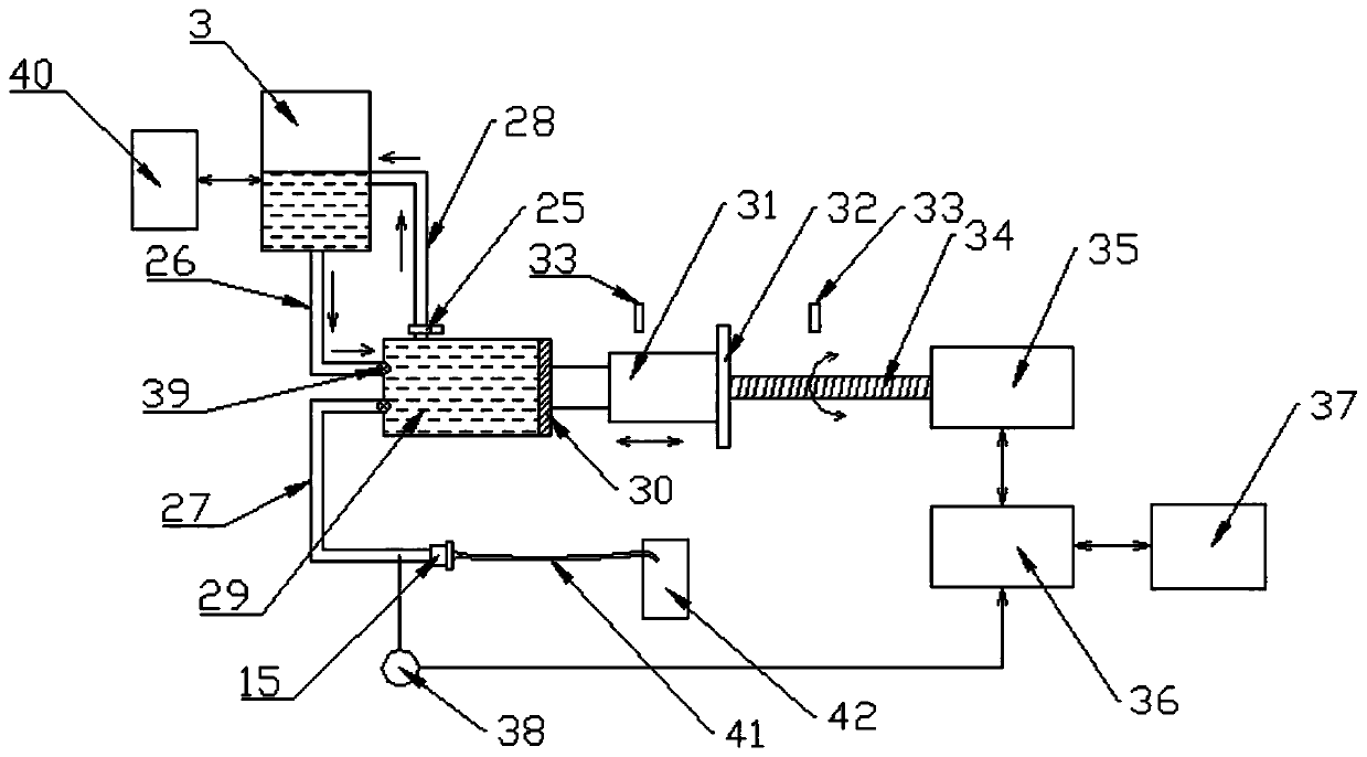
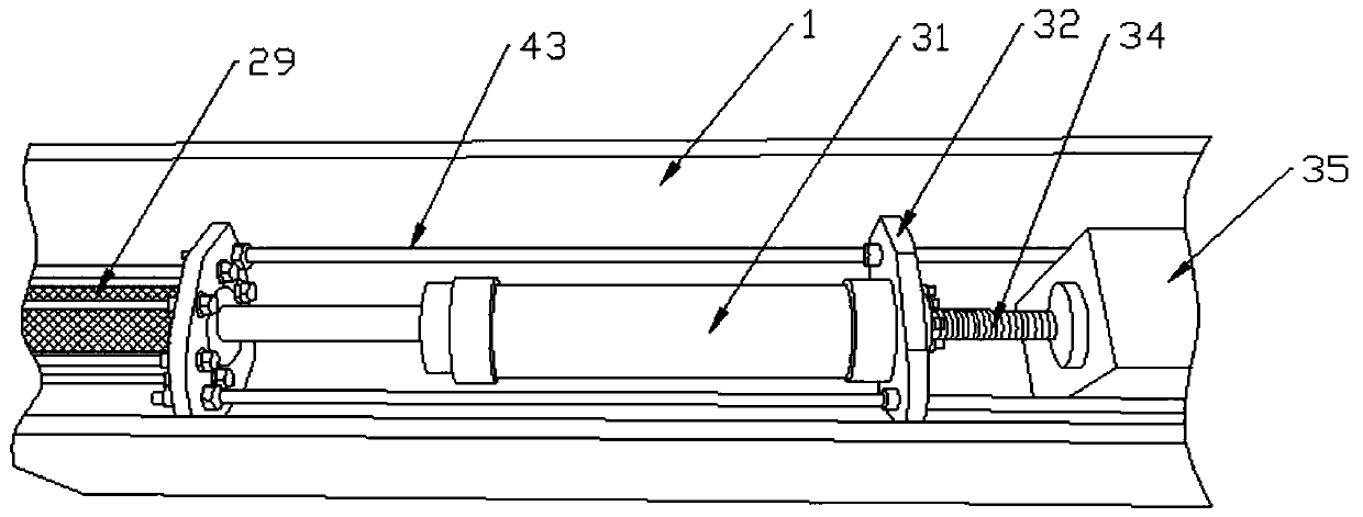
The invention discloses a test device for the conduit burst pressure under static conditions and a working method thereof and belongs to the technical field of medical apparatus detection. The test device includes a body, wherein the body is internally provided with a pressure device container, one end of the pressure device container is in sliding connection with a liquid push device, the other end of the pressure device container is provided with a liquid inlet and a liquid outlet, the liquid outlet is communicated with a conduit interface, a ball screw transmission mechanism is formed between the liquid push device and a driving device, one end opposite to the driving device is provided with a constant temperature water bath tank and a water pipeline, a liquid outlet pipe is internallyprovided with a pressure sensor, the driving device is provided with a controller, and the pressure sensor is connected with a controller of the driving device. The invention further discloses the working method of the test device. The test device is advantaged in that the fluid with the stable rate is supplied into the conduit, the conduit is guaranteed to be in the constant temperature environment, and test requirement in accord with the industrial standards is met.

Description

technical field [0001] The invention belongs to the technical field of medical device inspection, and specifically relates to a test device for the burst pressure of a catheter under static conditions and a working method thereof, which is suitable for testing the burst pressure of a power injection catheter under static conditions. Background technique [0002] In clinical applications, catheter products are often used to quickly and stably inject liquids such as contrast agents and high-concentration drugs into patients under high pressure conditions, in order to achieve clinical purposes such as imaging and treatment. Common power injection catheters include intravascular catheters such as contrast catheters, microcatheters, support catheters, central venous catheters, implantable drug delivery devices, and some trocar peripheral catheters. [0003] Contrast catheters are often used in surgical treatments such as radiological interventional diagnosis and treatment for ins...

Claims


Application Information

Patent Timeline
IPC IPC(8): G01N3/12G01N3/02
Inventor 刘斌张博万敏李元彧李坎园刘维俊张翔孙建军
Owner 山东省医疗器械产品质量检验中心
Learn More