
Computer visual image projection device

A computer vision and projection device technology, applied in projection devices, supporting machines, mechanical equipment, etc., can solve the problems of poor seismic performance, difficult to adjust the image projection angle, lack of auxiliary heat dissipation, etc., to improve service life and facilitate auxiliary heat dissipation. Effect

Inactive Publication Date: 2019-06-21
YANTAI ZHIXING INTPROP CONSULTATION SERVICES CO LTD
View PDF4 Cites 3 Cited by
  • Summary
  • Abstract
  • Description
  • Claims
  • Application Information

AI Technical Summary

Problems solved by technology

[0006] The purpose of the present invention is to provide a computer vision image projection device in order to solve the above problems, which solves the problem that the existing projector is not easy to adjust the image projection angle, and the problem that the projector has poor seismic performance when it is installed and used, and When the equipment is used for a long time, it is prone to high temperature, lack of auxiliary heat dissipation, etc.

Method used


Image

  • Computer visual image projection device
  • Computer visual image projection device
  • Computer visual image projection device

Examples


Embodiment Construction

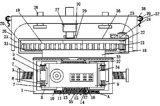
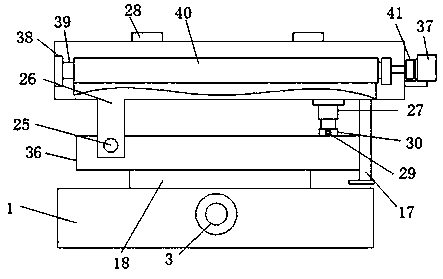
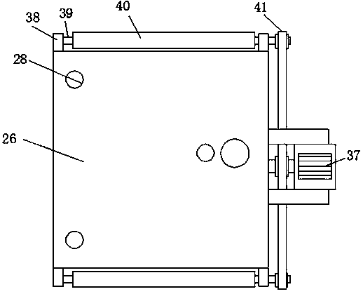
[0026] Such as Figure 1-5 As shown, this specific embodiment adopts the following technical solutions: a computer vision image projection device, including a fixed cavity 1, the fixed cavity 1 is a cuboid structure, and screw rods 2 are threaded on both sides of the fixed cavity 1, One ends of the two screw rods 2 penetrate to both sides of the fixed chamber 1 and are fixedly connected with bearings 4, and the other ends of the two bearings 4 are respectively fixedly connected to one side of the two clamping blocks 5, so The upper and lower ends of the clamping block 5 are elastically connected to the connecting rods 7 through the first spring 6 respectively, and the other ends of the two connecting rods 7 respectively penetrate to the outside of the clamping block 5 and are fixedly connected to the clamping rods 8 A projector 9 is nested and connected between the two clamping blocks 5 and inside the fixed cavity 1, the upper end of the fixed cavity 1 is fixedly connected wit...


PUM


Abstract

The invention discloses a computer visual image projection device. The computer visual image projection device comprises a fixed cavity, wherein the fixed cavity is of a cuboid structure; screw rods are connected to the two sides of the interior of the fixed cavity in a threaded manner; one ends of the two screw rods penetrate through the two sides of the interior of the fixed cavity and are fixedly connected with bearings respectively; a rotating disc is driven by a first servo motor according to the design, and the lower end of the rotating disc is fixedly connected to the inner part of thefixed cavity through a rotating rod, so that the irradiation angle of the projector in the fixed cavity is effectively adjusted by three hundred sixty degrees by rotating the first servo motor, the projection angle of the image of the projector is changed conveniently, and the projector is more practical; a first spring is fixedly connected with a clamping rod through a connecting rod, and the clamping rod is elastic, so that the projector can be effectively protected and damped, and higher safety is achieved; and a first heat dissipation fan and a second heat dissipation fan are designed, sothat auxiliary heat dissipation on the projector can be carried out more conveniently, and the service life of the projector is effectively prolonged.

Description

[0001] Technical field: [0002] The invention belongs to an image projection device, in particular to a computer vision image projection device, and belongs to the technical field of computer vision image projection. [0003] Background technique: [0004] Computer vision is a simulation of biological vision using computers and related equipment. When computer vision is used, it often projects and plays some images. At this time, the use of a projector is used. The structure of the traditional projector projection device It is relatively fixed and can only be irradiated at a single angle. It cannot effectively project the visual image projected by the projector onto other projection boards according to the needs. It is inconvenient to disassemble, and the shock absorption performance is poor, and there are improvements. Moreover, when the traditional image projector works continuously for a long time, high temperature is easily generated inside the projector, and there is no e...

Claims


Application Information

Patent Timeline
IPC IPC(8): G03B21/54G03B21/16F16M11/04F16M11/08F16M11/10F16M11/18F16M13/02
Inventor 牟晓丹
Owner YANTAI ZHIXING INTPROP CONSULTATION SERVICES CO LTD
Learn More