
Turning plate type hidden door stopper for auxiliary heat dissipation of switch cabinet

An auxiliary heat dissipation and flap-type technology, which is applied in the cooling/ventilation of substation/switchgear, details of substation/switch layout, electrical components, etc., to achieve good effect, easy industrial manufacturing, and small size

Pending Publication Date: 2022-04-01
STATE GRID SHANDONG ELECTRIC POWER
View PDF1 Cites 0 Cited by
  • Summary
  • Abstract
  • Description
  • Claims
  • Application Information

AI Technical Summary

Problems solved by technology

However, the traditional door stopper products, as well as the new technology announced by the patent, still only limit the function of the door stopper to the scope of fixing the door body in the open state
So far, there is no door catch product or patent that has such a design purpose: in addition to satisfying the need to fix the door body in an open state, it can also achieve the purpose of fixing the door body in a concealed state by changing its installation position. Function

Method used


Image

  • Turning plate type hidden door stopper for auxiliary heat dissipation of switch cabinet
  • Turning plate type hidden door stopper for auxiliary heat dissipation of switch cabinet
  • Turning plate type hidden door stopper for auxiliary heat dissipation of switch cabinet

Examples


Embodiment example 1

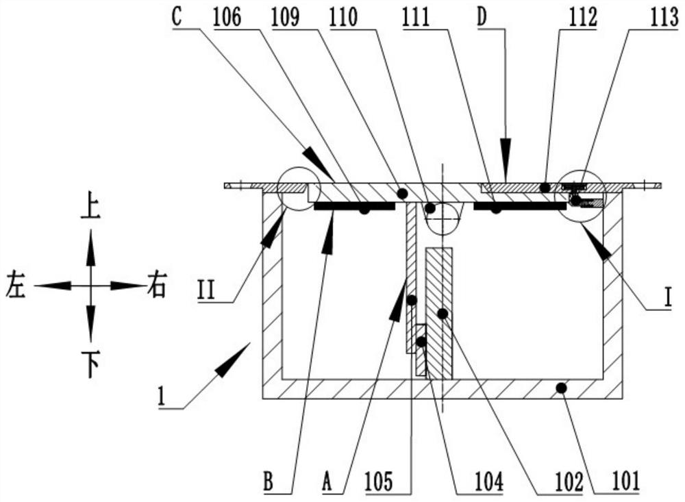
[0055] A flap-type concealed door stopper for auxiliary heat dissipation of switch cabinets, consisting of a shell door stopper 1 and a door stopper 2 used in conjunction with it; see figure 1 , 4.

[0056] The door stopper 1 includes a housing 101, a cover plate 112 is installed on the upper end of the housing 101, and a hole is opened on the cover plate 112; in the housing 101, a limit plate 102 is fixedly installed at the bottom, and the limit plate 102 is a guide Magnetic material; in the housing 101, the top is provided with a flap 109, the bottom of the flap 109 is provided with a support 110, and the flap 109 is flexibly connected with the housing 101 through the bracket 110; direction; the lower surface of the turnover plate 109 is fixed with a positioning magnet 111 relative to the right side of the bracket 110, and a fixed magnet 106 is fixedly installed with respect to the left side of the bracket 110; between the fixed magnet 106 and the bracket 110 A large baffle...

Embodiment example 2

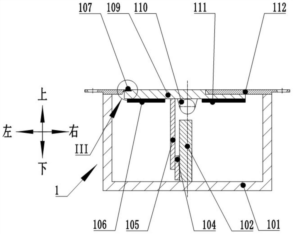
[0083]The difference between this case and Example 1 is that the switch device of the flap-type concealed door stopper for auxiliary heat dissipation of the switchgear described in the present invention is a rotary sheet switch device 107; the rotary sheet switch device 107 includes a rotary Sheet 72, rotating shaft 75, pull ring a76; The rotating shaft 75 is inserted into the cover plate hole 74, and can rotate freely in the horizontal direction, and its upper surface is not higher than the upper surface of the turning plate 109 or both are flush; the upper part of the rotating shaft 75 A pull ring a76 is arranged slightly lower than the upper surface of the turnover plate 109. When the pull ring a76 is in a horizontal position, it is located in the pull ring groove 78, and its upper surface is not higher than the upper surface of the turnover plate 109 or both are flush; a76 is movably connected with the rotating shaft 75, and can rotate arbitrarily between the horizontal pos...

Embodiment example 3

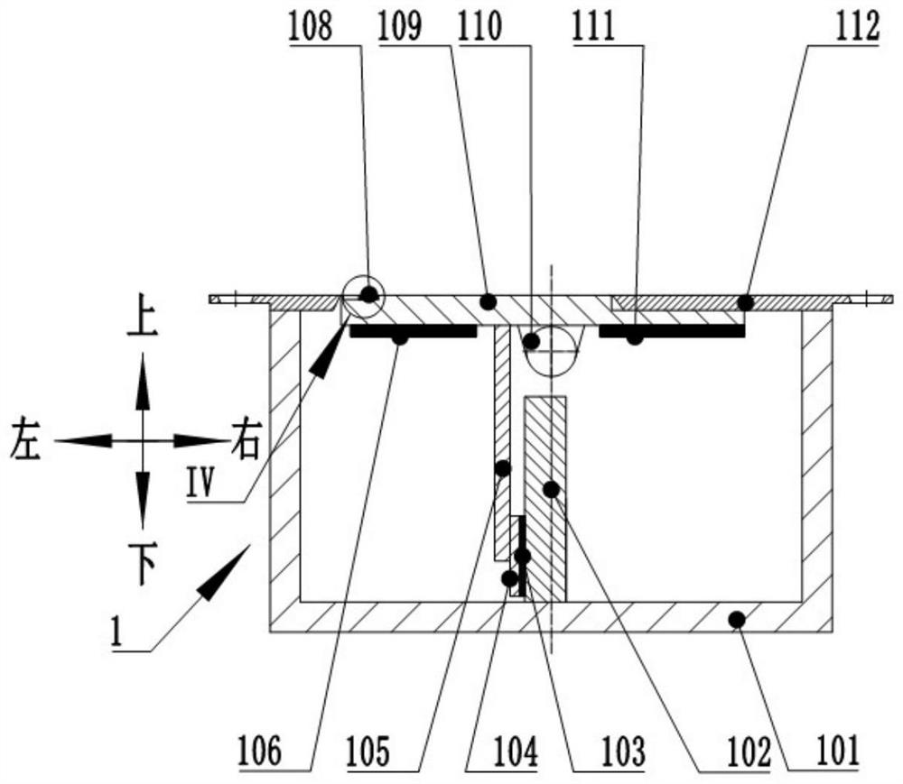
[0098] The difference between this case and the implementation cases 1 and 2 is that the flap type concealed door stopper used for auxiliary heat dissipation of the switchgear according to the present invention has a switch device including a pull ring b108 and a locking magnet 103; the pull ring b108 and the flip The plate 109 is movably connected and can rotate freely around the connection point in the vertical direction; when the pull ring b108 is in the horizontal position, it is located in the pull ring groove 78, and its upper surface is not higher than the upper surface of the flap 109 or both are flush; The locking magnet 103 is fixed on the small baffle 104; when the door stopper 1 is in the hidden state, the locking magnet 103 is in contact with the limiting plate 102 and is attracted together.

[0099] Its specific use method is as follows:

[0100] Install the door stopper 1 on the ground behind the door, such as Figure 5 As shown, the upper surface of the door s...


PUM


Abstract

The invention relates to a turning plate type hidden door stopper for auxiliary heat dissipation of a switch cabinet. The turning plate type hidden door stopper comprises a door stopper and a door stopper head, the door stopper comprises a shell, an open cover plate is arranged at one end of the shell, and a positioning plate and a turning plate are arranged in the shell. The turning plate is movably connected with the shell; a baffle plate, a fixed magnet and a positioning magnet are arranged on the turning plate; the door suction head comprises an outer cylinder and a suction plate; a positioning cylinder is mounted in the outer cylinder, and an elastic device and a movable pressing plate are mounted in the positioning cylinder; the movable pressing plate is connected with the suction plate through a bolt; a fixing cylinder is arranged on the suction plate, an elastic device is arranged on the fixing cylinder, and the fixing cylinder extends into the outer cylinder and is pressed by a fixing pressing plate. The door stopper is completely hidden below a mounting surface when not working, can be mounted at a position with a narrow space, can fix a door in an open state and also has a function of fixing the door in an unclosed state, is safe to use, and does not influence opening and closing of a door body. The door stopper head of the door stopper is provided with the buffering device, and the buffering force of the door stopper head can be adjusted according to different use environments.

Description

technical field [0001] The invention belongs to the technical field of door stoppers, in particular to a flap-type hidden door stopper for auxiliary heat dissipation of a switch cabinet. Background technique [0002] When the switchgear is in hot weather, the internal electrical components are seriously heated, and sometimes it is necessary to partially open the door of the switchgear to help dissipate heat. [0003] The door stopper is a daily tool for fixing the door body, including a door stopper bracket installed on the door body and a door stopper base installed on the ground or wall. Traditional door stoppers can be divided into four categories: column type, suction sheet type, vertical and horizontal type, electromagnetic and electric type. [0004] The application date is 2017.08.01, and the patent application number CN201710647651.3 discloses an invisible door stopper, which can be installed anywhere behind the door to keep the door open; when the door stopper is n...

Claims


Application Information

Patent Timeline
IPC IPC(8): H02B1/30H02B1/38H02B1/54H02B1/56
CPCE05C17/56E05F5/08E05Y2999/00Y02T10/70
Inventor 亓富军彭静王军李彪于贺贺庞伟超赵福强孙筱轩苏超吕贵龙刘聪陈玉廖誉翔张海娟陈海燕满丽
Owner STATE GRID SHANDONG ELECTRIC POWER
Learn More