
An internal installation structure of a vehicle charger and the vehicle charger

An on-board charger and installation structure technology, applied in electric vehicle charging technology, charging stations, vehicle parts, etc., can solve the problems of long installation time, low work efficiency, and circuit board time-consuming, etc. The effect of heat dissipation, improving installation efficiency and reducing the number of uses

Active Publication Date: 2021-05-07
深圳市瀚强科技股份有限公司
View PDF6 Cites 0 Cited by
  • Summary
  • Abstract
  • Description
  • Claims
  • Application Information

AI Technical Summary

Problems solved by technology

[0003] In view of the deficiencies in the prior art, the purpose of the invention is to provide an internal installation structure of a vehicle charger and a vehicle charger, so as to solve the problem that the circuit board of the charger proposed in the above-mentioned background technology is connected with the bracket by bolts to ensure that the circuit The installation stability of the board, the number of bolts required to fix a circuit board is large, so it takes a long time to install, and it takes a lot of time to disassemble the circuit board. The problem of low work efficiency is that the invention guarantees tight connection While being solid, it greatly reduces the amount of bolts used, improves assembly efficiency, and is easy to disassemble

Method used


Image

  • An internal installation structure of a vehicle charger and the vehicle charger
  • An internal installation structure of a vehicle charger and the vehicle charger
  • An internal installation structure of a vehicle charger and the vehicle charger

Examples


Embodiment Construction

[0020]In order to make the invention, the creation characteristics, the purpose and efficacy are readily understood, and in connection with the specific embodiments, the invention is further illustrated.

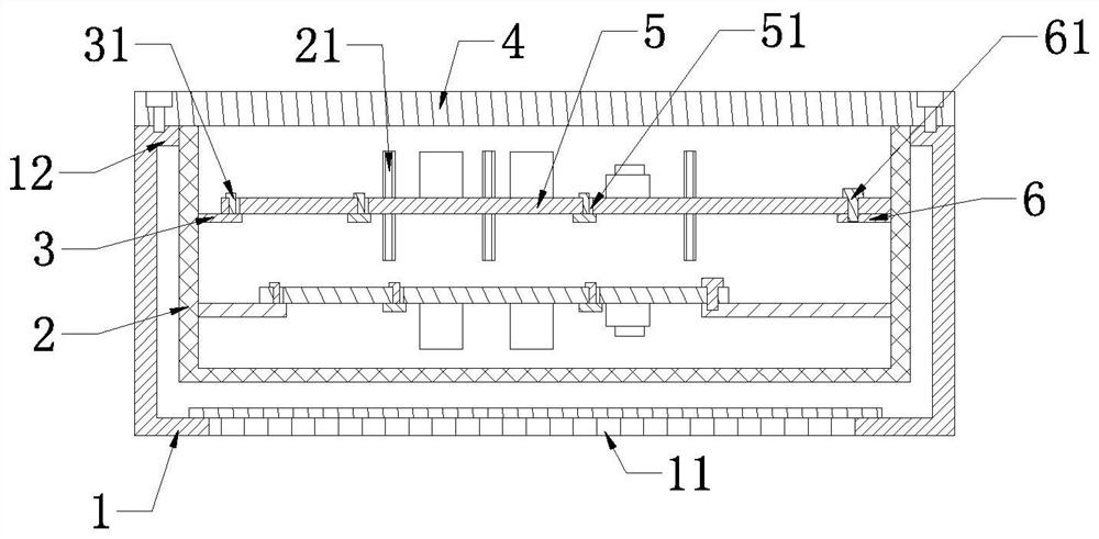
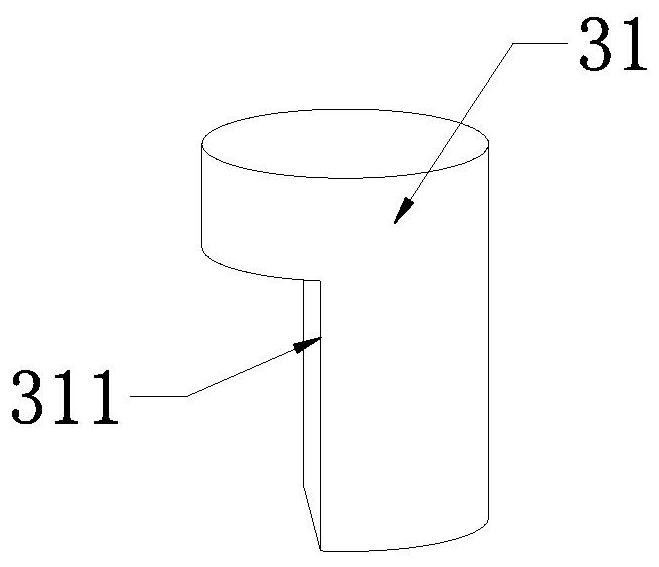
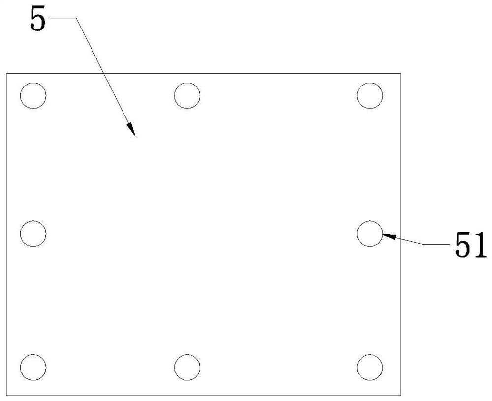
[0021]SeeFigure 1 - Figure 3The invention provides a technical solution: an internal mounting structure of a vehicle charger, including a casing 1, a casing 1 inside a web frame 2, and the structure of the mesh frame 2 facilitates air flow, thereby facilitating heat dissipation of the casing 1. The first connecting plate 3 in which the three adjacent sidewalls in the inside of the frame 2 is fixedly extended inwardly extended, and the second connecting plate 6, the first connecting plate 3, and the first connection plate 3, and the first The number and position of the dicing plate 6 is provided as needed, and the upper end of the first connection plate 3 fixes the card cassette 31, and the network frame 2 is provided with a circuit board 5 and the circuit board 5 is provided in the f...


PUM


Abstract

The invention provides an internal installation structure of a vehicle charger and a vehicle charger. The installation structure includes a box body, a screen frame is fixed inside the box body, and three adjacent side walls of the four side walls inside the screen frame are fixed to The first connecting plate extending inward and the second connecting plate extending inward is fixed on the other side wall. The upper end of the first connecting plate is fixed with a clamping cylinder. A connecting plate and the upper end of the second connecting plate, the clamping cylinder is arranged inside the circuit board and extends to the upper end of the circuit board, a locking bolt is installed on the upper end of the circuit board, and the locking bolt passes through the circuit board and is connected with the second The connecting plate is connected by threads, the upper end of the box body is fixed with an end cap and the end cap seals the upper opening of the box body, the invention greatly reduces the use of bolts while ensuring the tightness of the connection, improves the assembly efficiency, and is convenient Disassemble.

Description

Technical field[0001]The present invention is an internal mounting structure and a car charger within the vehicle charger, which belongs to the technical field of charger.Background technique[0002]The vehicle charger has the power of electric vehicle power batteries, safety, automatic charge, and the charging can dynamically adjust the charging current or voltage parameters according to the data provided by the battery management system, perform the corresponding action, complete the charging process, with energy saving Emission reduction, and the demand for controlling atmospheric pollution, new energy vehicles are gradually commercialized in the market, of which the car charger OBC, voltage converter DCDC, high voltage power distribution PDU is an important part of electric vehicles, in-vehicle charger OBC, voltage converter The electronic components such as DCDC, high voltage distribution PDU are mounted on a circuit board inside the charger, and the four weeks of the circuit boa...

Claims


Application Information

Patent Timeline
Patent Type & Authority Patents(China)
IPC IPC(8): B60L53/20B60L53/22H05K7/20
CPCB60L53/20B60L53/22H05K7/2089Y02T10/70Y02T10/7072Y02T90/14
Inventor 吴峰杨小春
Owner 深圳市瀚强科技股份有限公司
Learn More