Fuel injection valve for injecting a gaseous and/or liquid fuel

A technology for fuel injection valves and liquid fuels, which can be used in fuel injection devices, special fuel injection devices, charging systems, etc., and can solve problems such as limited installation space

Active Publication Date: 2019-06-21
ROBERT BOSCH GMBH
View PDF8 Cites 3 Cited by
  • Summary
  • Abstract
  • Description
  • Claims
  • Application Information

AI Technical Summary

Problems solved by technology

However, the available instal

Method used


Image

  • Fuel injection valve for injecting a gaseous and/or liquid fuel
  • Fuel injection valve for injecting a gaseous and/or liquid fuel
  • Fuel injection valve for injecting a gaseous and/or liquid fuel

Examples


Embodiment Construction

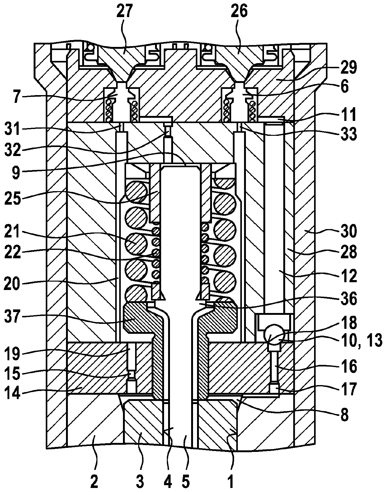
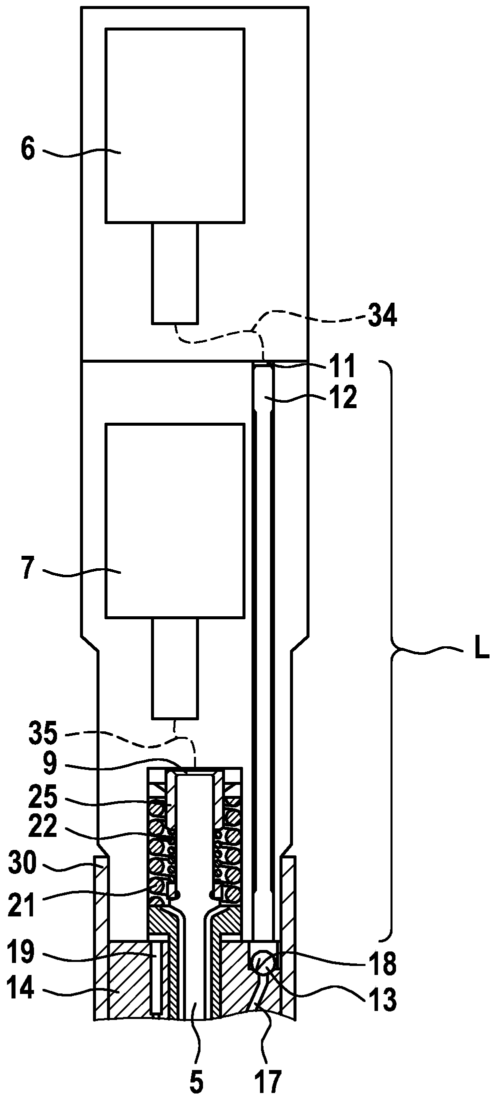
[0026] exist figure 1 A fuel injection valve for injecting gaseous fuel and / or liquid fuel into a combustion chamber of an internal combustion engine as shown in includes a nozzle body 2 having a central bore 1 in which a first valve element is reciprocally received 3. The first valve element 3 also has a central bore 4 . In this central bore the second valve element 5 is guided reciprocally. The central bore 4 of the first valve element 3 can be charged with liquid fuel, while the central bore 1 of the nozzle body 2 can be charged with gaseous fuel. Thus, gaseous fuel can be introduced into the combustion chamber by the reciprocating movement of the first valve element 3 , while the injection of liquid fuel can be achieved by the reciprocating movement of the second valve element 5 .

[0027] The first valve element 3 cooperates with a first sealing seat 23 which is formed by the nozzle body 2 . If the first valve element 3 is lifted from the sealing seat 23, it releases ...


PUM


Abstract

The invention relates to a fuel injection valve for injecting a gaseous and/or a liquid fuel into a combustion chamber of an internal combustion engine, comprising a first valve element (3) accommodated such that the frist valve element can perform reciprocating movements in a central bore (1) of a nozzle body (2), and a second valve element (5) accommodated such that the second valve element canperform reciprocating movements in a central bore (4) of the first valve element (3), and control valves (6, 7) for the hydraulic pilot control of the two valve elements (3, 5), wherein each valve element (3, 5) is assigned a control chamber (8, 9), which can be relieved via a control valve (6, 7). According to the invention, a further valve (10), which can be controlled hydraulically via the control valve (6), is arranged at least between a control chamber (8) and a control valve (6) used to relieve the control chamber (8).

Description

technical field [0001] The invention relates to a fuel injection valve for injecting gaseous fuel and / or liquid fuel into a combustion chamber of an internal combustion engine, having the features of the preamble of claim 1 . Such fuel injectors are also known as dual fuel injectors, dual mass injectors or dual fuel injectors. Background technique [0002] Fuel injectors of the above-mentioned type generally have two reciprocating nozzle needles guided in a nest, which serve to release and close the injection openings for the different fuels. The actuation of this valve is relatively expensive, since a control valve must be present for each nozzle needle. Furthermore, the two control valves must be time-precisely coordinated with each other. [0003] A fuel metering valve for an internal combustion engine is known from laid-open publication DE 10 2014 225 167 A1, which has a housing in which a nozzle needle is arranged longitudinally displaceable, which is configured in a ...

Claims


Application Information

Patent Timeline
IPC IPC(8): F02M21/02F02M43/04
CPCF02M43/04F02M45/086F02M21/0248F02D19/06F02M2200/46Y02T10/30
Inventor B·莱布斯勒
Owner ROBERT BOSCH GMBH
Why Eureka
Try Eureka