Eureka AIR delivers breakthrough ideas for toughest innovation challenges, trusted by R&D personnel around the world.

Bracket bending forming device

A bending forming and bending technology, which is applied in the direction of forming tools, perforating tools, and ejection equipment, can solve the problems such as the difficulty of springback correction of the bending punch and bending die structure, and achieve a reasonable structural design and easy removal and repair of the mold , the effect of reducing the degree of bending springback

Inactive Publication Date: 2019-06-25
SUZHOU INST OF INDAL TECH
View PDF0 Cites 0 Cited by
  • Summary
  • Abstract
  • Description
  • Claims
  • Application Information

AI Technical Summary

Problems solved by technology

[0003] The bending method of the parts in the prior art is a mold structure that uses the upper and lower relative movements of the bending punch and the bending die to bend the parts into shape. In this bending method, after the bending is completed, the workpiece will rebound, and the workpiece will rebound after rebounding. , it is more difficult to correct the springback of the bending punch and bending die structure, and it is impossible to implement effective correction bending in the horizontal direction

Method used


Image

  • Bracket bending forming device
  • Bracket bending forming device
  • Bracket bending forming device

Examples


Embodiment Construction

[0030] The invention will be described in more detail hereinafter with reference to the accompanying drawings showing embodiments of the invention. However, this invention may be embodied in many different forms and should not be construed as limited to the embodiments set forth herein. Rather, these embodiments are provided so that this disclosure will be thorough and complete, and will fully convey the scope of the invention to those skilled in the art. In these drawings, the size and relative sizes of layers and regions may be exaggerated for clarity.

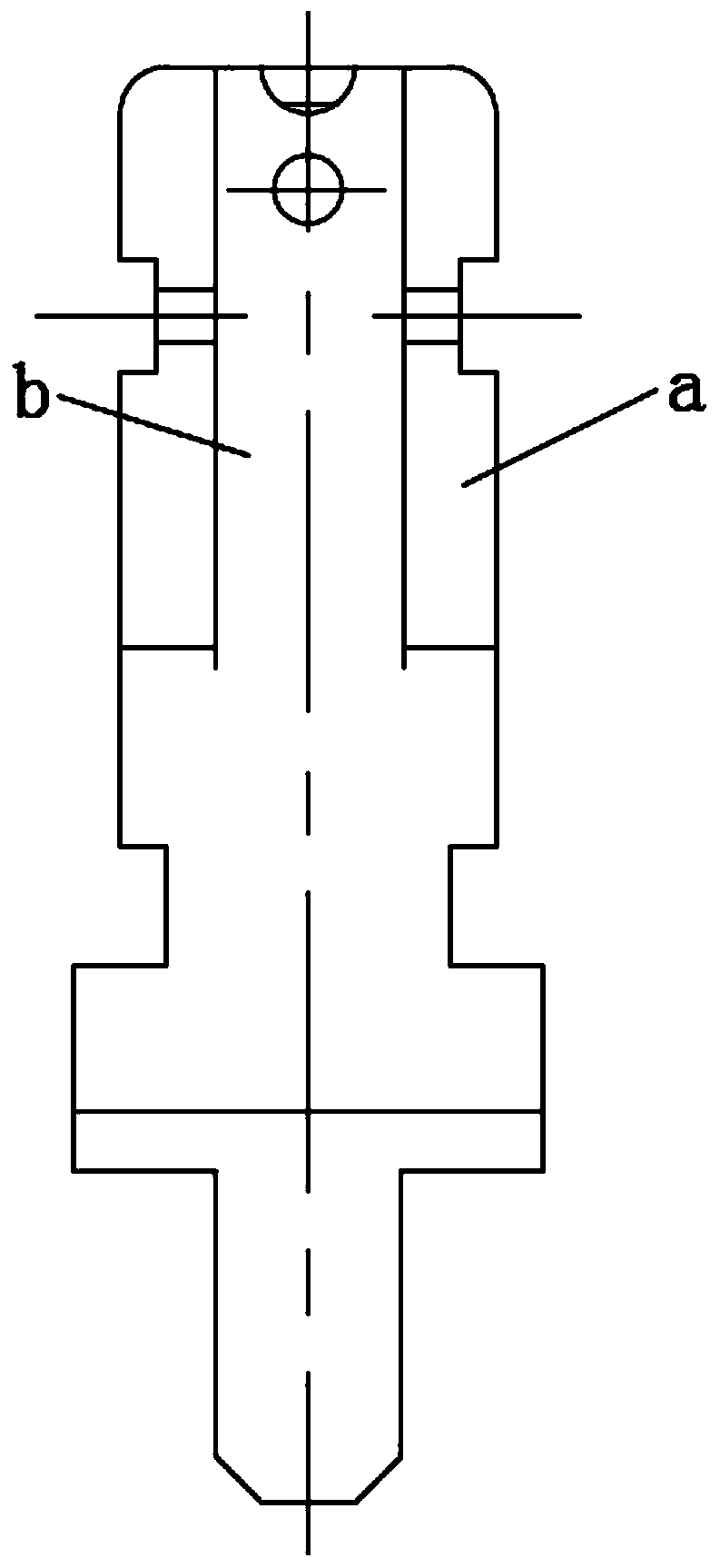
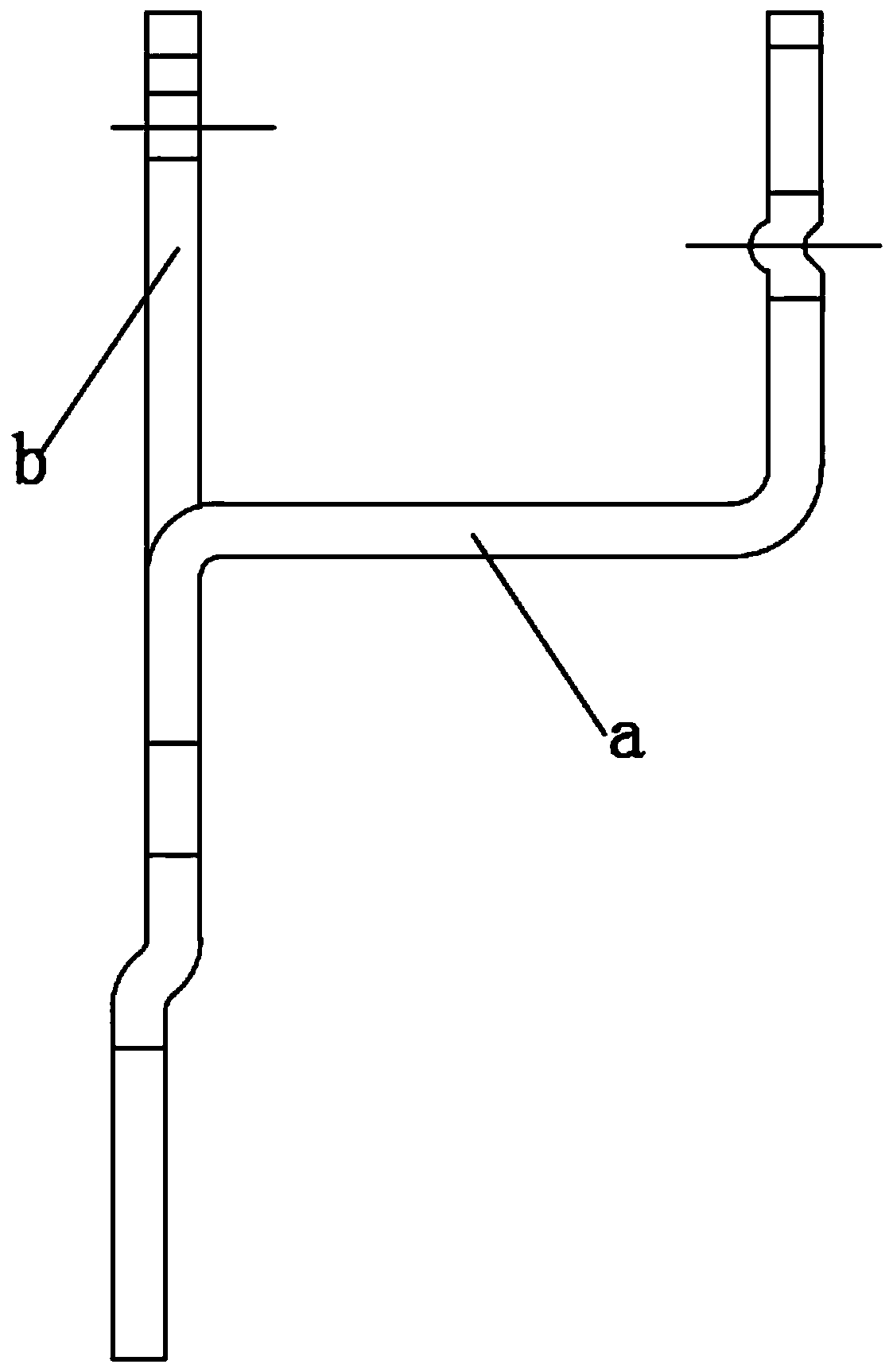
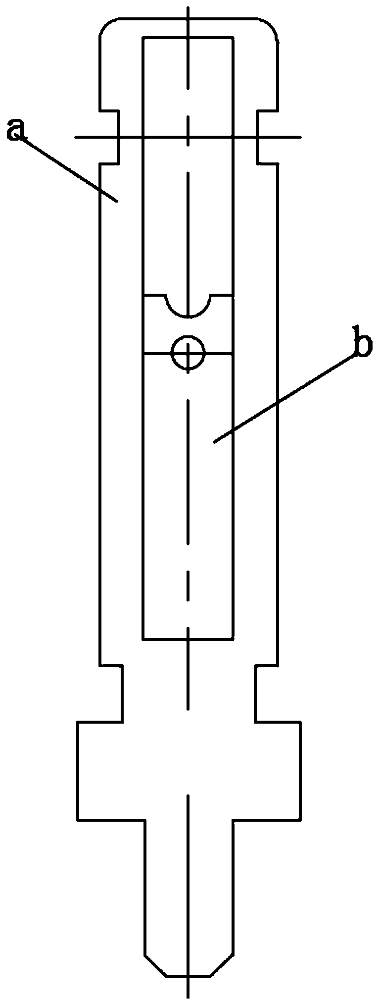
[0031] The invention provides a bracket bending forming device, which is mainly used for processing multi-angle bent brackets; refer to Figure 1-3 The bracket shown in is a supporting part on an electrical switch, the following is the Figure 1-3 The stent shown in is taken as an example to describe the stent bending forming device provided by the present invention in detail. Of course, the stent bending forming device pr...


PUM


Abstract

The invention provides a bracket bending forming device comprising an upper die, a lower die and a feeding mechanism arranged between the upper die and the lower die. A die hole corresponding to the upper die and the lower die is internally provided with a guide pin technology hole punching assembly, a blanking waste cutting process mechanism, a bending process mechanism and a cutting process mechanism sequentially; the bending process mechanism includes at least one set of bending components including a bending male die, a bending female die, a tapered wedge block and a bending lower die drawing core, the upper ends of the bending male die and the tapered wedge block are arranged on the upper die side by side, and the bending female die and the bending lower die drawing core are arrangedside by side on the lower die; and the upper die and the lower die are opposite up and down, the lower end of the tapered wedge block and the upper end of the bending lower die drawing core are opposite and are matched through an inclined face. A to-be-processed part is arranged on the lower die, the upper end of the bending lower die drawing core extends out of the upper surface of the lower die,and the side face abuts against the side with the machined part.

Description

technical field [0001] The invention relates to the technical field of mold design, in particular to a bracket bending forming device. Background technique [0002] The bracket is an indispensable part of electrical products, the output of the product is large, and the dimensional accuracy is required to be high. Therefore, in terms of stamping process design and mold structure determination, it is important to ensure the angular accuracy of the bent parts after bending. According to the deformation characteristics of bending parts, springback is easy to occur when parts are bent, and springback is inevitable. Therefore, measures can only be taken to reduce springback. The usual method is to design a reasonable bending die structure. [0003] The bending method of the parts in the prior art is a mold structure that uses the upper and lower relative movements of the bending punch and the bending die to bend the parts into shape. In this bending method, after the bending is c...

Claims


Application Information

Patent Timeline
Patent Type & Authority Applications(China)
IPC IPC(8): B21D35/00B21D37/08B21D28/34B21D28/14B21D7/16B21D45/04
Inventor 梁士红
Owner SUZHOU INST OF INDAL TECH
Why Eureka
Eureka Blog
Learn More