Stirrup automatic conveying device for reinforcement cage welding

A technology of automatic conveying device and steel cage, applied in the direction of auxiliary devices, welding equipment, auxiliary welding equipment, etc., can solve the problems of low automation, high labor cost, low transportation efficiency, etc., and achieve high automation and high work efficiency Effect

Inactive Publication Date: 2019-06-25
CHINA MINSHENG ZHUYOU
View PDF13 Cites 4 Cited by
  • Summary
  • Abstract
  • Description
  • Claims
  • Application Information

AI Technical Summary

Problems solved by technology

[0004] The technical problem to be solved by the present invention is to provide an automatic stirrup conveying device to solve the problems of low transportation efficiency and low degree of automation in the prior art that rely on manual delivery of good stirrups on the hoop bending machine to the steel cage welding equipment and technical issues such as high labor costs

Method used


Image

  • Stirrup automatic conveying device for reinforcement cage welding
  • Stirrup automatic conveying device for reinforcement cage welding
  • Stirrup automatic conveying device for reinforcement cage welding

Examples


Embodiment Construction

[0025] The present invention will be described in detail below with reference to the accompanying drawings. The description in this part is only exemplary and explanatory, and should not have any limitation on the protection scope of the present invention. In addition, according to the description of this document, those skilled in the art can correspondingly combine the features in the embodiments of this document and in different embodiments.

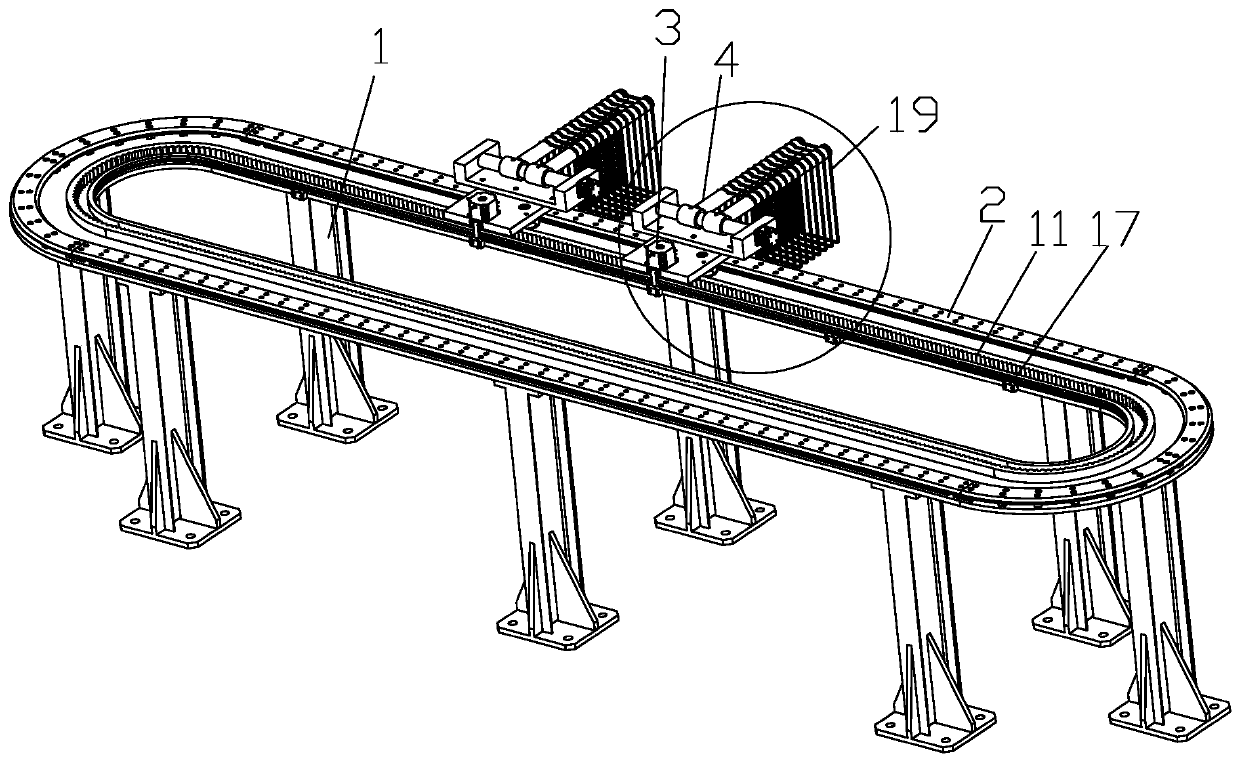
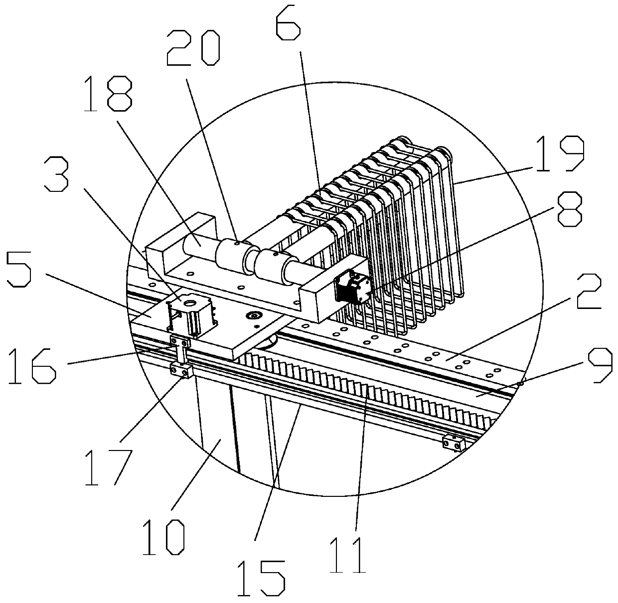
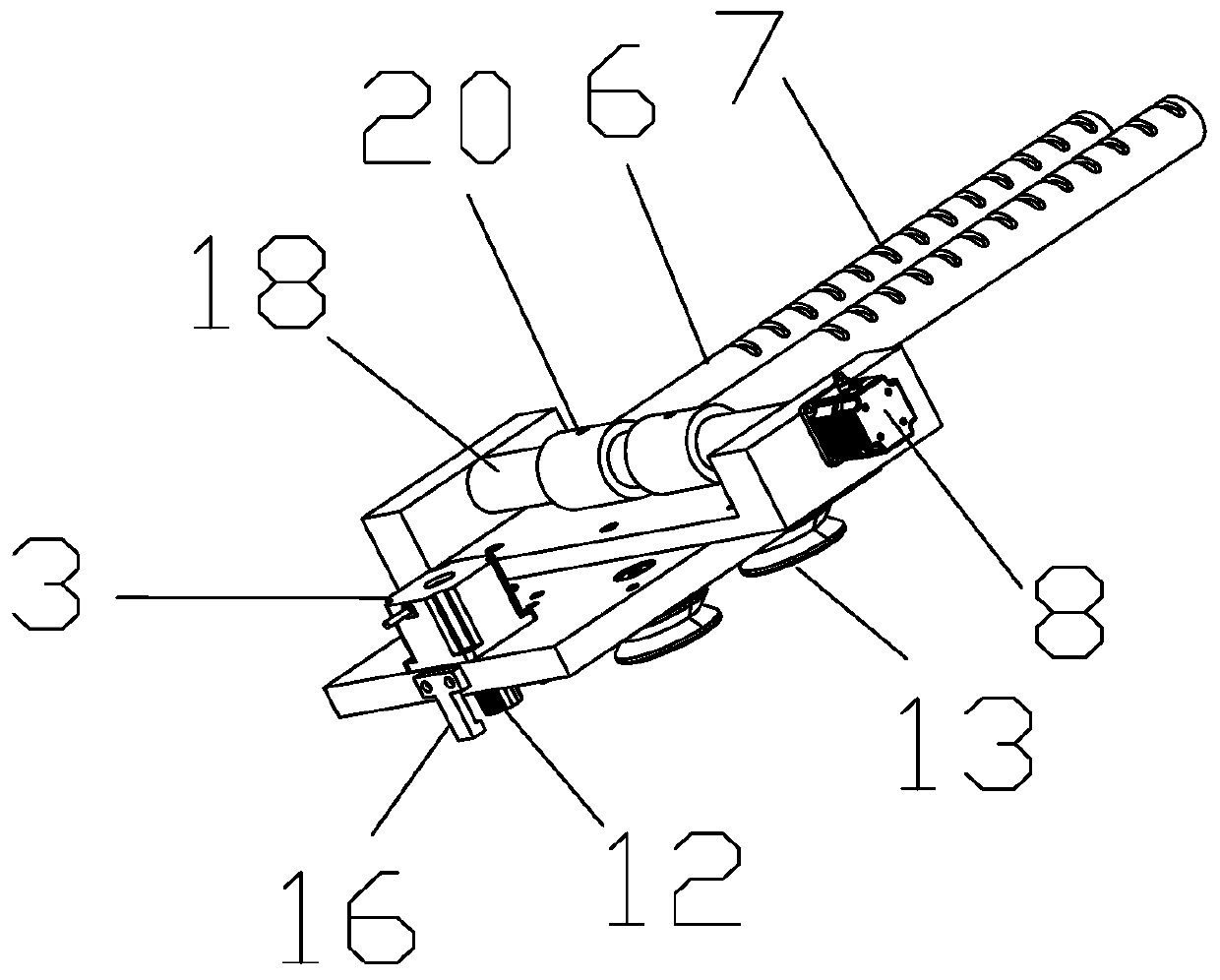
[0026] Reference schematic figure 1 In this embodiment, the automatic stirrup conveying device for steel cage welding includes a support 1, a guide rail 2, a power mechanism, a transmission mechanism, and a hanger 4. The support 1 includes a plurality of vertical pillars 10 and a fixing plate 9 on the top of the pillar 10, and the guide rail 2 is fixed on the fixing plate 9. The hanging rack 4 includes a fixed part 5 and a hanging rod 6 which are fixedly connected, and the fixed part 5 is arranged on the guide rail 2. See also schematic...


PUM


Abstract

The invention discloses a stirrup automatic conveying device for reinforcement cage welding. The stirrup automatic conveying device comprises supports, a guide rail, a power mechanism, a transmissionmechanism and handing racks, wherein the handing racks comprise fixed parts and handing rods which are fixedly connected; the fixed parts are arranged on the guide rail; the transmission mechanism isarranged on the top sides of the supports and on the fixed parts; and the power mechanism is arranged on the fixed parts and drives the handing racks to move along the guide rail through the transmission mechanism. The stirrup automatic conveying device is arranged on a production line and is arranged between a stirrup bending machine and a reinforcement cage automatic welding machine, the functions of stirrup temporary storage and stirrup automatic conveying can be achieved, stirrups can be automatically conveyed according to the production takt of reinforcement cage welding, the automation degree is high, and working efficiency is high.

Description

Technical field [0001] The invention belongs to the technical field of steel cage processing machinery. Specifically, the invention relates to an automatic stirrup conveying device for welding of steel cages. Background technique [0002] In the prior art, the steel cage is mostly completed by machine welding in a factory. The raw materials of the longitudinal reinforcement and the stirrup are processed separately, and then transported to the welding equipment to weld the stirrup to the longitudinal reinforcement. The automatic hoop bending machine first bends the material of the stirrup into a stirrup according to the preset size, and then manually transfers the bent stirrup to the steel cage welding equipment for welding with the longitudinal reinforcement. This operation method of manual transfer and conveying of stirrups is time-consuming and labor-intensive, has relatively low efficiency, increases labor costs, and easily brings safety hazards that the stirrups may slip and...

Claims


Application Information

Patent Timeline
Patent Type & Authority Applications(China)
IPC IPC(8): B23K37/00
Inventor 黄岸薛英杰
Owner CHINA MINSHENG ZHUYOU
Why Eureka
Try Eureka