
Automatic wooden handle tip planing machine

A technology of automatic turning and cutting machine, which is applied in the direction of woodworking lathes, wood processing equipment, manufacturing tools, etc. It can solve the problems of increasing labor intensity of workers, error of cutting length, and rising of defective products, so as to avoid the trouble of cutting materials for workers , reduce the workload, and ensure the effect of smooth use

Pending Publication Date: 2019-06-25
TANGSHAN YANNAN SHOVEL MAKING
View PDF0 Cites 2 Cited by
  • Summary
  • Abstract
  • Description
  • Claims
  • Application Information

AI Technical Summary

Problems solved by technology

[0002] At present, the commonly used wooden handle turning machine is a single planer, which is carried out by pushing the lever artificially.
One end of the wooden pole needs a turning tip, and the other end needs a car shell or a round head. The worker needs to turn one end of the tip first, and then turn the other end of the shell or round head after the car is finished. Repeat the action twice, and it is a manual operation. The workers need to rest for a period of time. When the workers operate, they pick up the wooden handle—the tip of the car (the shell, the round head)—and stack the wooden handle. It is necessary to carry the wooden handle repeatedly, which increases the labor intensity of the worker. Since the whole operation is by manpower, the forward force of the turning tip is different, the length of the turning tip will also be different, and the probability of defective products will increase. The same wooden handle is turned twice or so, and the coaxiality is also the same. will fall

Method used


Image

  • Automatic wooden handle tip planing machine
  • Automatic wooden handle tip planing machine
  • Automatic wooden handle tip planing machine

Examples


Embodiment Construction

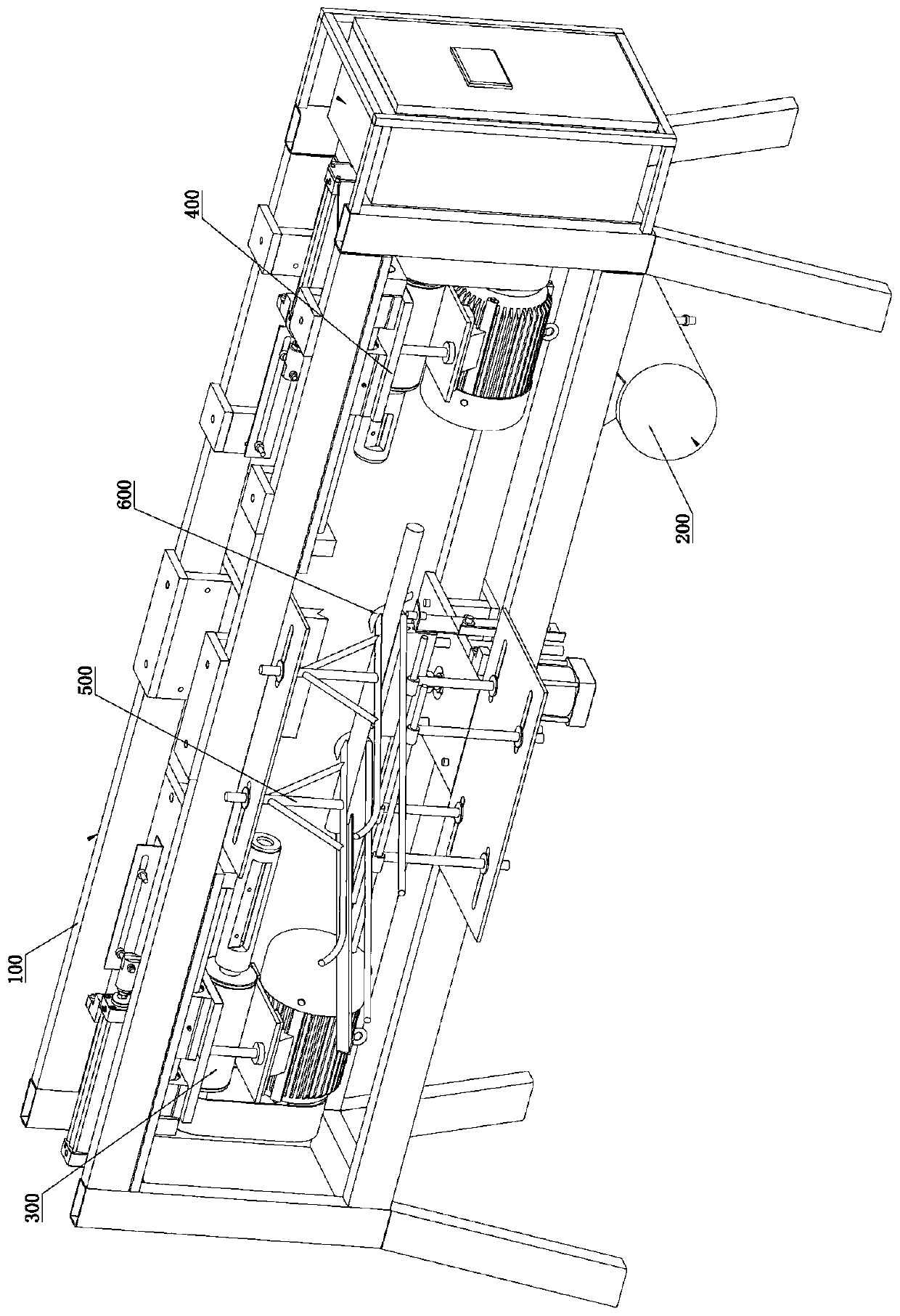
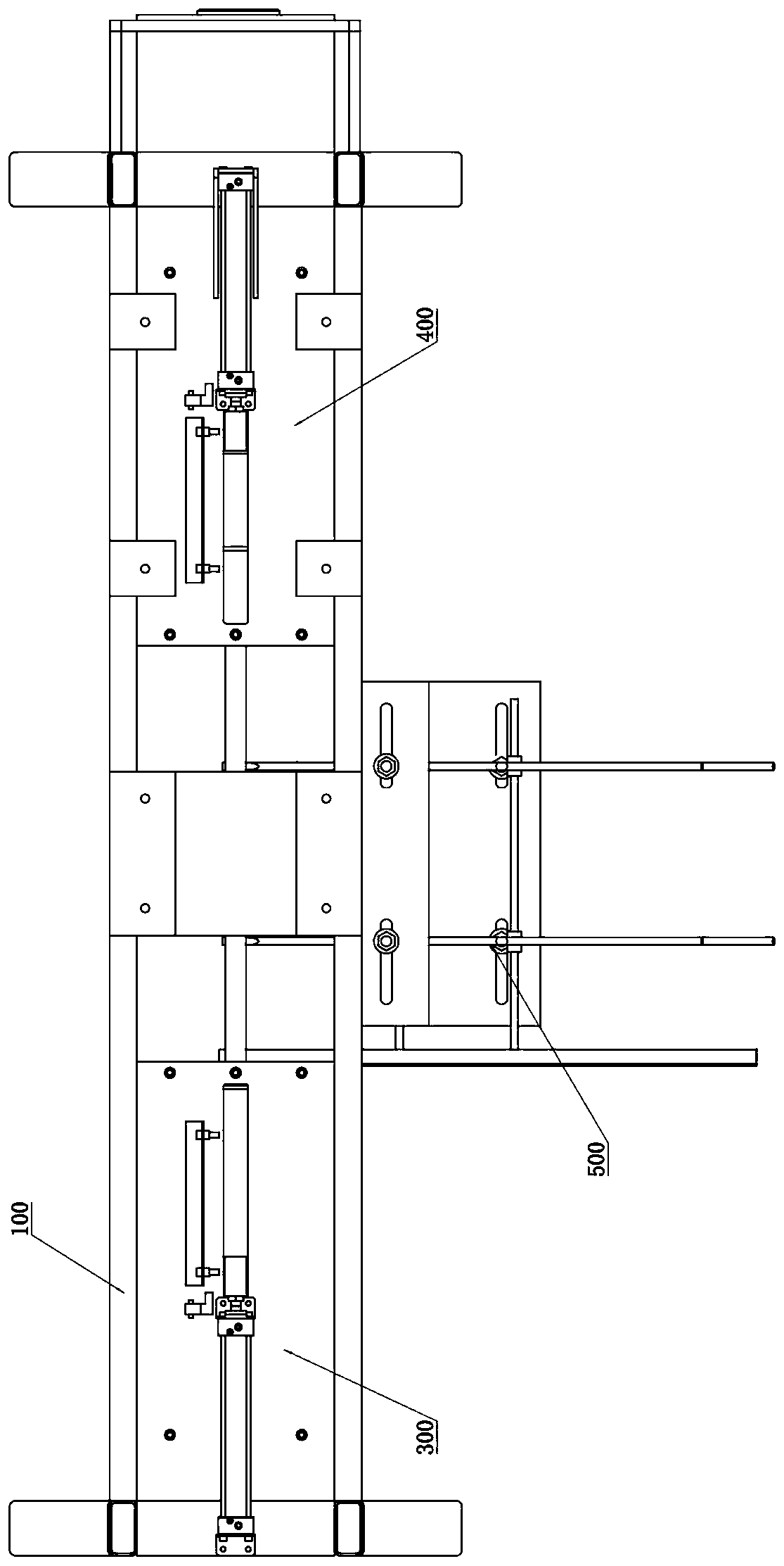
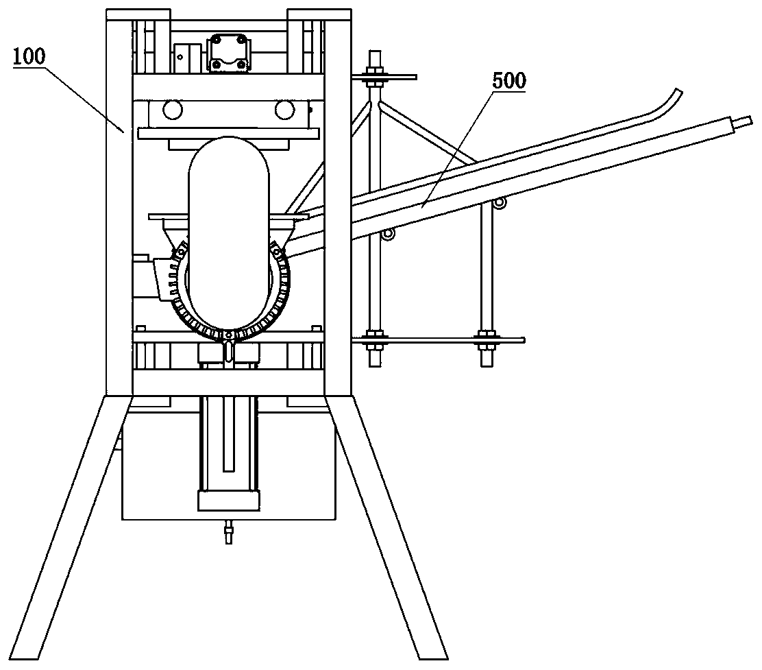
[0026] Such as Figure 1 to Figure 3 As shown, this specific embodiment adopts the following technical solutions: a wooden pole automatic turning machine, including a main body frame 100, an air storage tank 200, a turning part 300, a car shell part 400, a clamp part 500 and a stripping part 600; The lower right side of the main body frame 100 is fixedly connected with an air storage tank 200; the tail part 300 is fixedly connected to the upper left side inside the main body frame 100; The shell part 400 is fixedly connected to the upper right side inside the main frame 100; the clamp part 500 is located in the center between the tip part 300 and the car shell part 400, and the clamp part 500 is fixedly connected to the center of the main frame 100; the stripper The part 600 is provided on the lower rear side of the jig part 500 .

[0027] Such as Figure 4As shown, the specific structure of the tip part 300 includes a motor-4, a transmission shaft-5, a tip planer 6, a shiel...


PUM


Abstract

The invention discloses an automatic wooden handle tip planing machine. The automatic wooden handle tip planing machine comprises a main frame, an air storage tank, a tip planing part, a shell planingpart, a fixture part and a discharge part. The left and right ends of the tip planing machine are both provided with planing heads, one end serves as the tip planing head, and the other end serves asthe shell or round head planing head. The planing heads include the round head planing head, the tip planing head and the shell planing head, has the various types of shapes and can meet the requirements for various types of wooden clubs. The planing heads can be replaced just by loosening fasteners. The application range is wide. The two ends of the automatic wooden handle tip planing machine can conduct processing simultaneously. One working position is omitted. Manpower is saved. A worker just needs to place a workpiece on a bracket. Frequent feeding and discharging by workers are omitted.The workload of the workers is reduced. According to the automatic wooden handle tip planing machine, the air storage tank is used for storing air and storing a certain quantity of compressed air andensures the continuity of output air flow. Smooth application of the machine is ensured. According to the automatic wooden handle tip planing machine, a discharge device acting through self-weight isdesigned. The automatic wooden handle tip planing machine implements the automatic discharging process after completion of product processing. The trouble of manual discharging is omitted. The workload of staff is reduced.

Description

technical field [0001] The invention relates to a wooden pole turning machine, in particular to an automatic wooden pole turning machine. Background technique [0002] The wooden handle turning machine commonly used at present is a single planer, and pushes the lever hard artificially to carry out turning. One end of the wooden pole needs a turning tip, and the other end needs a car shell or a round head. The worker needs to turn one end of the tip first, and then turn the other end of the shell or round head after the car is finished. Repeat the action twice, and it is a manual operation. The workers need to rest for a period of time. When the workers operate, they pick up the wooden handle—the tip of the car (the shell, the round head)—and stack the wooden handle. It is necessary to carry the wooden handle repeatedly, which increases the labor intensity of the worker. Since the whole operation is by manpower, the forward force of the turning tip is different, the length o...

Claims


Application Information

Patent Timeline
Patent Type & Authority Applications(China)
IPC IPC(8): B27C7/00B27C7/04B27C7/06
Inventor 付长强付长义
Owner TANGSHAN YANNAN SHOVEL MAKING
Learn More