Shifting device

A technology of shifting device and gear position, which is applied in the direction of control device, transmission device control, transportation and packaging, etc., can solve problems such as difficult to grasp the selected gear position, improve visual recognition, suppress misoperation, and improve operability Effect

Inactive Publication Date: 2019-06-25
HONDA MOTOR CO LTD
View PDF8 Cites 0 Cited by
  • Summary
  • Abstract
  • Description
  • Claims
  • Application Information

AI Technical Summary

Problems solved by technology

[0005] However, in the above-mentioned conventional shifting device, since the operating portion is reset to the reference position, there is a problem that it is difficult to grasp the shift position that can be selected from the current shift position.

Method used


Image

  • Shifting device
  • Shifting device
  • Shifting device

Examples


no. 1 approach

[0034] [vehicle]

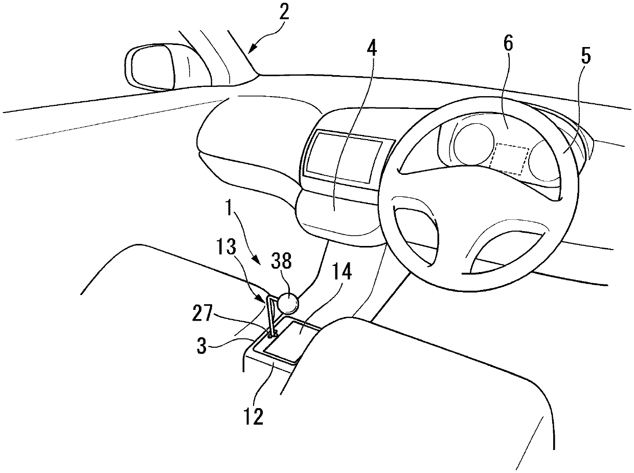
[0035] figure 1 It is a perspective view of the vehicle interior showing the arrangement of the shift device 1 . Unless otherwise specified, directions such as front, rear, left, and right in the following description are assumed to be the same as the directions of the vehicle.

[0036] Such as figure 1 As shown, the shifting device 1 is a shift-by-wire mode. Specifically, the shift device 1 drives an actuator (not shown) based on a range switching signal generated in accordance with an input operation of an operator (driver), thereby switching the gears of an automatic transmission (not shown). gear. The shifting device 1 is arranged in the vehicle 2 at a place where an operator's hands are easy to touch (for example, the center console 3 ). It should be noted that, for example, the shift device 1 may also be arranged on the instrument panel 4 .

[0037]

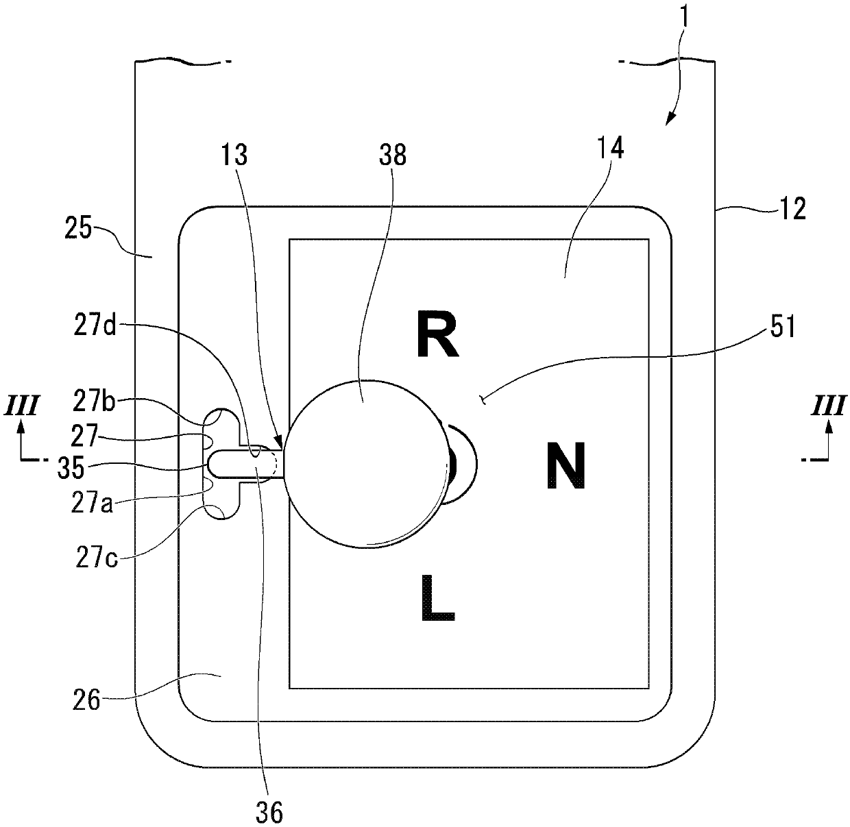
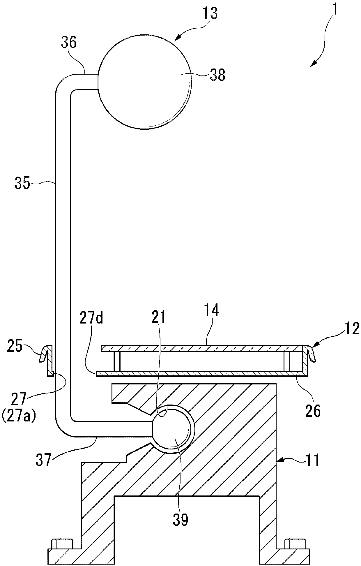
[0038] figure 2 It is a plan view of the shift device 1 . image 3 With figure 2 Equivale...

no. 2 approach

[0112] Next, the above-mentioned second embodiment of the present invention will be described. Figure 11 It is a figure which shows an example of the display pattern of the range display area 51 in 2nd Embodiment. In the following description, the same reference numerals are assigned to the same configurations as those in the above-mentioned embodiment, and description thereof will be omitted.

[0113] Such as Figure 11 As shown, in the display unit 14 of this modified example, a position image (R position image) representing a reverse position among the position images of the drive system positions can be displayed on the drive system display unit 51b. On the other hand, the display unit 14 is configured to be able to switch between the shift images showing the drive range (L range image, D range image, etc.) showing the drive range on the drive system display unit 51c. That is, in the present embodiment, the shift position image representing forward movement is displayed...


PUM


Abstract

A shifting device capable of improving operability is provided. The shifting device includes a display portion (14) that displays a gear image corresponding to a gear of the automatic transmission, ashift lever (13) that moves from the reference position based on the gear image to select a gear position and is capable of being reset to the reference position in a state where the operating force is released, and a control unit which controls a display mode of the gear image displayed on the display unit (14). The display unit (14) has a selection gear display unit (51a) displaying a gear imageindicating the current gear, a drive system display portion (51b, 51c) and a non-drive system display portion (51d), and the drive system display portion (51b, 51c) and the non-drive system display portion (51d) display a gear image that can be selected by the shift lever (13). The control unit displays only the gear images that can be selected by the shift lever (13) on the drive system displayunits (51b, 51c) and the non-drive system display unit (51d).

Description

technical field [0001] The present invention relates to shifting devices. Background technique [0002] In recent years, a so-called shift-by-wire system that switches the gear position of an automatic transmission based on an electric signal has attracted attention as a shift device for a vehicle. In the shift device of the shift-by-wire system, an operation unit (for example, a shift lever) is operated based on a shift display displayed on a display unit (for example, an escutcheon, etc.). Then, the gear is switched by driving the actuator based on the electric signal generated by the operation of the operation part. [0003] As the operating part used in the above-mentioned shifting device, there is known a so-called instantaneous type in which the operating part is returned to the reference position by releasing the operating force acting on the operating part after the operating part is operated (after the gear is selected). Operation section (for example, refer to Ja...

Claims


Application Information

Patent Timeline
Patent Type & Authority Applications(China)
IPC IPC(8): B60K20/02B60K20/08F16H59/08
Inventor 山中史景大城孝之西村勇纪
Owner HONDA MOTOR CO LTD
Why Eureka
Try Eureka