Assembly supporting floating body crossed splicing type water surface photovoltaic power generation system

A photovoltaic power generation system and support system technology, applied in the photovoltaic field, can solve the problems of difficulty in forming a floating water surface photovoltaic overall power generation scheme, difficulty in ensuring the stability and safety of the power station, and inability to provide electrical equipment support, etc., so as to save aisle floating body , The overall stability is excellent, the effect of reducing the shadow spacing

Pending Publication Date: 2019-06-25
CHANGJIANG SURVEY PLANNING DESIGN & RES
View PDF5 Cites 14 Cited by
  • Summary
  • Abstract
  • Description
  • Claims
  • Application Information

AI Technical Summary

Problems solved by technology

In terms of structure, this patent is similar to the aforementioned patent, and the use of independent aluminum alloy parts to support the photovoltaic module may cause damage to the module; in terms of generality, the floating body cannot provide effective electrical equipment support, and it is difficult to form a floating water surface photovoltaic overall power generation scheme
[0009] Due to the above-mentioned problems in the existing floating surface photovoltaic floating body technology, it is difficult to ensure the stability and safety of the photovoltaic power station in the case of further cost reduction

Method used


Image

  • Assembly supporting floating body crossed splicing type water surface photovoltaic power generation system
  • Assembly supporting floating body crossed splicing type water surface photovoltaic power generation system
  • Assembly supporting floating body crossed splicing type water surface photovoltaic power generation system

Examples


Embodiment Construction

[0052] The present invention will be further described below in conjunction with the accompanying drawings and specific embodiments.

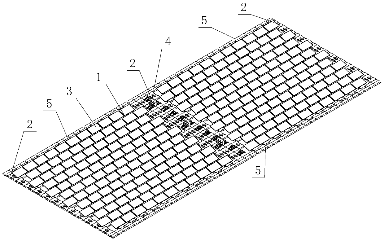
[0053] Such as figure 1 As shown, a component-supported floating body cross-splicing water surface photovoltaic power generation system of the present invention includes a component-supported floating body device and an equipment floating body device. The component-supported floating body device is used to install and support photovoltaic modules 3, and electrical equipment 4, cables and anchoring systems are fixed Installed on the equipment floating body device; the component support floating body device and the equipment floating body device are spliced ​​together.

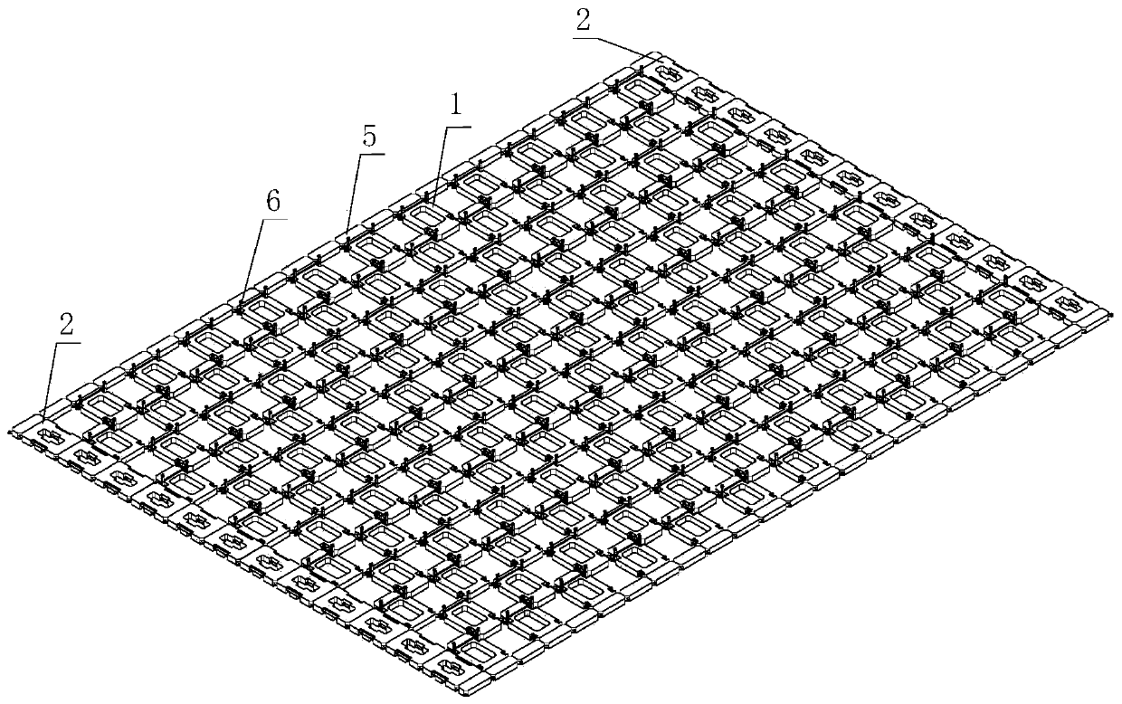
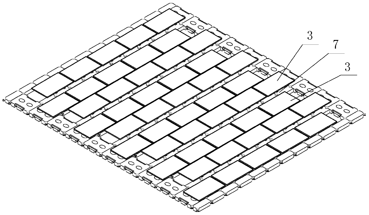
[0054] Such as Figure 2-4 As shown, in this embodiment, the module supporting floating body device includes multiple rows of module supporting floating bodies 1 that are spliced ​​together crosswise, and each row of module supporting floating bodies 1 includes a plurality of mo...


PUM


Abstract

The invention relates to an assembly supporting floating body crossed splicing type water surface photovoltaic power generation system. The photovoltaic power generation system comprises an assembly supporting floating body device and a device floating body device. The assembly supporting floating body device comprises a plurality of rows of assembly supporting floating bodies crossed and splicedtogether; the corresponding assembly supporting floating bodies between the two adjacent rows of assembly supporting floating bodies are spliced together alternately to form a firm net-shaped structure, the problem that collision damage is likely to be caused by non-transverse constraint between the multiple rows of assemblies in the prior art is solved, and the integrated stability is better; according to the connecting mode between the assembly supporting floating bodies, compared with the connecting mode of existing assemblies, the number of connecting points is few, the stability is better, and installing is more convenient. Important functions of a water surface photovoltaic station photovoltaic assembly, electrical equipment, a cable laying and anchoring system and a maintenance channel can be achieved, the consumption of floating bodies is lowered while the functionality is enhanced, the photovoltaic station manufacturing cost is saved, and the technical assurance is supplied topushing water surface photovoltaic market to achieve network surfing with fair price as soon as possible.

Description

technical field [0001] The invention relates to the field of photovoltaic technology, in particular to a cross-splicing water surface photovoltaic power generation system supported by floating bodies supported by components. Background technique [0002] Since its introduction in 2011, the floating surface photovoltaic power generation system has been rapidly popularized and applied due to its advantages of not occupying cultivated land and forest land, improving the utilization rate of water areas, and reducing water evaporation. Especially since 2016, the domestic floating water surface photovoltaic technology has developed rapidly under the support of the photovoltaic "leader" plan, and the rapid upgrading of products has promoted continuous breakthroughs in the key technologies of floating water surface photovoltaics. However, the promulgation of the "531" photovoltaic new policy has sounded the alarm for the industry: in order to achieve healthy and orderly development ...

Claims


Application Information

Patent Timeline
Patent Type & Authority Applications(China)
IPC IPC(8): B63B35/44H02S20/00
CPCY02E10/50
Inventor 刘海波袁博喻飞苏毅张涛金乾张顺刘爽段斐刘一亮
Owner CHANGJIANG SURVEY PLANNING DESIGN & RES
Why Eureka
Try Eureka