Unmanned-aerial-vehicle-and-oblique-photography-camera-combined aircraft-body upper surface checking method

A technology of oblique photography and aircraft fuselage, applied in the direction of aircraft component testing, etc., can solve the problems of time delay and manpower consumption, manpower and time consumption, and poor versatility, and achieve the goal of improving efficiency, strong versatility, and significant economic benefits Effect

Active Publication Date: 2019-06-25
CIVIL AVIATION FLIGHT UNIV OF CHINA +2
View PDF9 Cites 5 Cited by
  • Summary
  • Abstract
  • Description
  • Claims
  • Application Information

AI Technical Summary

Problems solved by technology

[0003] But it is not difficult to see that although the detection efficiency of this detection method has improved compared with manual detection, it still needs to disassemble the aircraft wing and put it into special detection equipment for detection. Such disassembly work is still relatively labor-intensive and labor-intensive. Time, when conducting regular routine inspections, those wings that do not need to be repaired in the first place still need to be disassembled, fully scanned, and installed in order to determine whether their surfaces are damaged. , installation and damage, which will bring greater workload to maintenance
[0004] In addition, different aircraft wing configurations are different. Faced with the huge fleet operated by airlines, more than a dozen special testing equipment are needed to meet the needs of maintenance personnel, and the versatility is not strong.

Method used


Image

  • Unmanned-aerial-vehicle-and-oblique-photography-camera-combined aircraft-body upper surface checking method
  • Unmanned-aerial-vehicle-and-oblique-photography-camera-combined aircraft-body upper surface checking method
  • Unmanned-aerial-vehicle-and-oblique-photography-camera-combined aircraft-body upper surface checking method

Examples


Embodiment 1

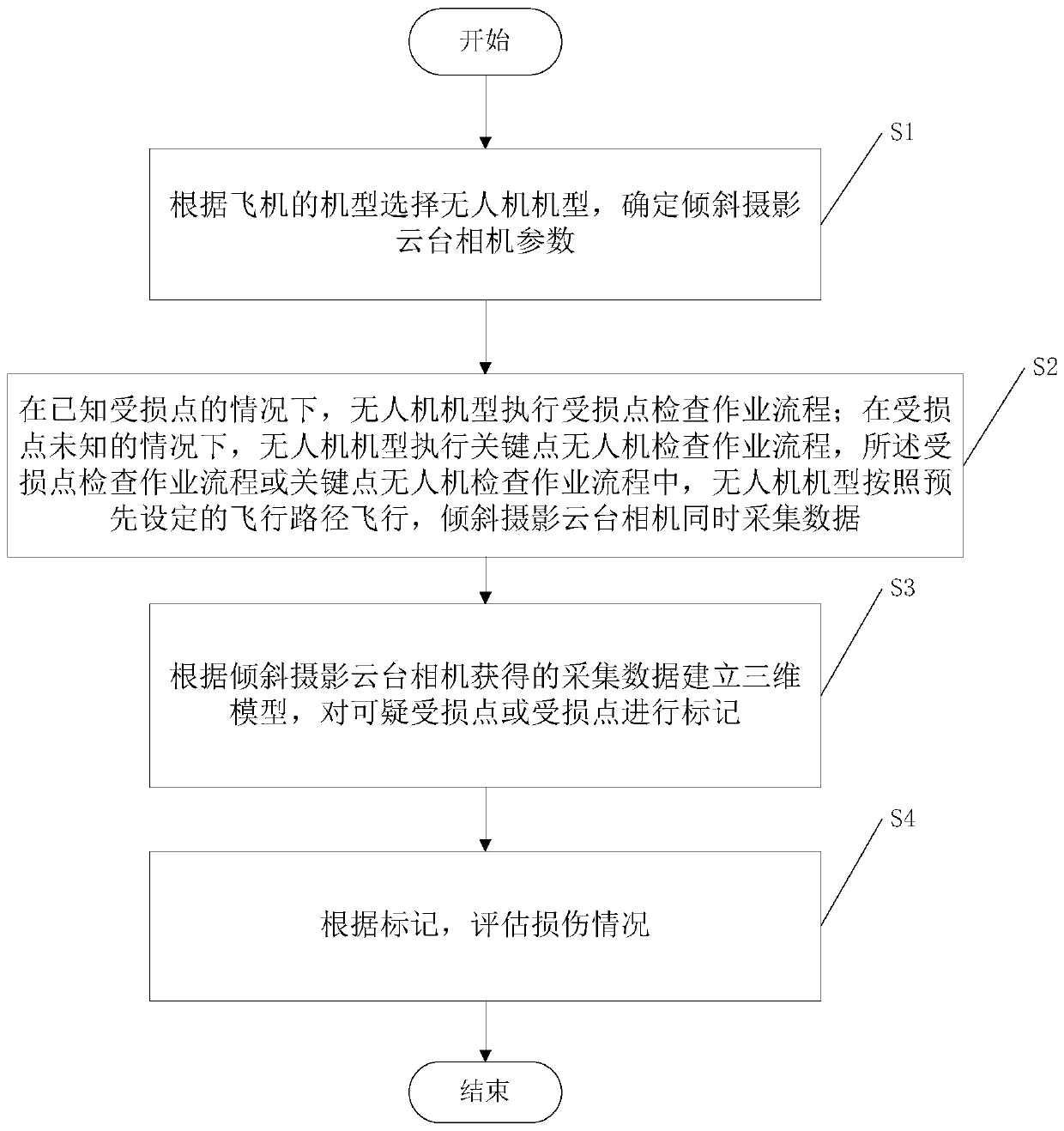
[0048] A method for inspecting the upper surface of an aircraft fuselage combined with an unmanned aerial vehicle tilting camera. The scope of inspection involves the upper half of the line between the nose and the center line of the wing and the three points of the tail, the wing, and the tail. The flow chart is as follows figure 1 shown, including the following steps:

[0049] S1, select the UAV model according to the model of the aircraft, and determine the camera parameters of the tilt photography pan / tilt.

[0050] The length of the wingspan and the length of the aircraft will directly affect the path length of the UAV operation. The longer the path length is, the larger the battery capacity of the UAV is required. Estimate the flight distance of the UAV, so as to estimate the minimum value of the battery capacity of the UAV. Considering the cost, when the battery capacity of the UAV model is greater than or equal to the minimum value of the battery capacity, it is consid...


PUM


Abstract

The invention relates to the field of civil-aviation-passenger-plane repairing and maintenance, in particular to an unmanned-aerial-vehicle-and-oblique-photography-camera-combined aircraft-body uppersurface checking method. The method includes the steps that 1, the type of an unmanned aerial vehicle is selected according to the type of an aircraft, and parameters of an oblique-photography holdercamera are determined; 2, a damaged-point checking operation procedure or a key-point unmanned-aerial-vehicle checking operation procedure are adopted, the unmanned aerial vehicle of the type flies according to a preset flight path, and the oblique-photography holder camera simultaneously collects data; 3, a three-dimensional model is built, and suspicious damaged points or damaged points are marked; 4, according to the marks, the damage condition is evaluated. According to the unmanned-aerial-vehicle-and-oblique-photography-camera-combined aircraft-body upper surface checking method, the unmanned aerial vehicle and the oblique holder photography camera are combined, checking strategies of upper surfaces of different aircraft types are given, parts of the aircrafts do not need to be disassembled, the upper surfaces of the aircrafts can be comprehensively, efficiently and accurately checked, data support is provided for planning follow-up maintenance schemes, and the aircraft maintenance efficiency is improved.

Description

technical field [0001] The invention relates to the field of repair and maintenance of civil aviation passenger aircraft, in particular to a method for inspecting the upper surface of an aircraft fuselage combined with an unmanned aerial vehicle tilting camera. Background technique [0002] With the continuous development of the aviation industry and aircraft manufacturing technology, more and more large jet airliners are put into civil aviation operation. Correspondingly, more requirements are put forward for the maintenance of the aircraft, especially the maintenance of the wings. There are a large number of Equipment has been successively developed to improve the efficiency of wing maintenance and inspection. In terms of wing maintenance, patent number CN201820470984 provides a wing detection device in aircraft maintenance, and patent number CN201520886926 provides a wing detection mechanism in aircraft maintenance. These patents protect specialized aircraft wing inspect...

Claims


Application Information

Patent Timeline
Patent Type & Authority Applications(China)
IPC IPC(8): B64F5/60
Inventor 潘卫军刘铠源宋歌王艺涓李直霖王少杰梁延安吴郑源邵楚涵
Owner CIVIL AVIATION FLIGHT UNIV OF CHINA
Why Eureka
Try Eureka