
Tower crane foundation conversion structure

A technology for transforming structure and foundation, applied in the direction of infrastructure engineering, construction, etc., can solve the problems of mixed fish and dragons, uneven technical capabilities of general contractors, etc., to achieve the effect of saving costs, wide application scope, and avoiding tight construction periods.

Pending Publication Date: 2019-06-25
GUANGDONG PANGYUAN ENG MACHINERY
View PDF0 Cites 0 Cited by
  • Summary
  • Abstract
  • Description
  • Claims
  • Application Information

AI Technical Summary

Problems solved by technology

[0002] With the development of the economy, the real estate industry has always been full of vitality. In the process of building construction, there are all kinds of tower cranes, and various brands are also dazzling, but there is a contradiction in the selection of tower crane models. , because the technical capabilities of the general contractors of many projects are uneven, and the professional subcontractors are also mixed. Some problems easily appear in the cooperation between the two, such as choosing the wrong model, and changing the model for economic benefits. Another example is that the tower crane has completed the foundation and pre-buried the outriggers, but it is found that there is no tower crane to install. Due to the pressure of the construction period, it has to be considered to replace it with other tower cranes of the same tonnage, etc.

Method used


Image

  • Tower crane foundation conversion structure
  • Tower crane foundation conversion structure
  • Tower crane foundation conversion structure

Examples


Embodiment Construction

[0014] The following will clearly and completely describe the technical solutions in the embodiments of the present invention with reference to the accompanying drawings in the embodiments of the present invention. Obviously, the described embodiments are only some, not all, embodiments of the present invention. Based on the embodiments of the present invention, all other embodiments obtained by persons of ordinary skill in the art without making creative efforts belong to the protection scope of the present invention.

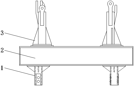
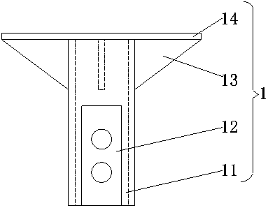
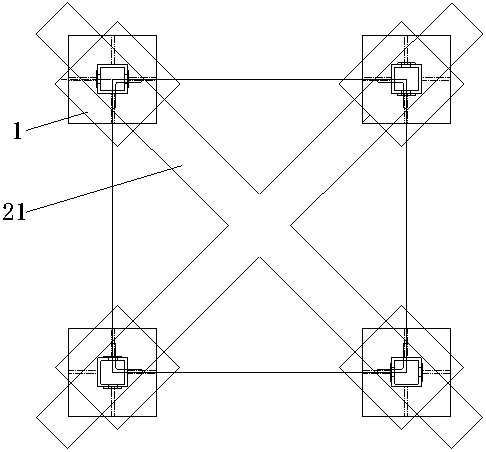
[0015] see Figure 1-3 , a tower crane foundation conversion structure, including a conversion stirrup 1, the conversion stirrup 1 is composed of a square tube main leg 11, a pin shaft plate 12, a rib plate 13 and a panel 14, and the side of the square tube main leg 11 is fixedly installed with a pin Shaft sticking board 12, pin shaft sticking plate 12 is arranged symmetrically on the outer surface of square pipe main limb 11, pin shaft sticking plate 12 and t...


PUM


Abstract

The invention discloses a tower crane foundation conversion structure. The tower crane foundation conversion structure is characterized in that each conversion stirrup is composed of a square pipe main limb, a pin shaft flitch, a reinforcing rib plate and a panel, wherein the pin shaft flitches are fixedly installed on the side faces of the square pipe main limbs; the tops of the square pipe mainlimbs are also respectively provided with the reinforcing rib plates and the panels; the tops of the panels are provided with supporting steel beams; fixed supporting legs are installed on the outer surfaces of the supporting steel beams in a clamping way; and the bottoms of the fixed supporting legs are movably assembled with cross-shaped bases. According to the tower crane foundation conversionstructure, the corresponding conversion stirrup is produced according to the characteristics of the pre-embedded supporting leg, the supporting steel beams are welded on the tops of the conversion stirrups, and the corresponding fixed supporting leg is welded according to an actual machine model to be installed, so that the compatibility problem of the pre-embedded supporting leg and an actually installed tower crane is solved; an original concrete pile cap foundation is fully utilized for convenient and quick installation of the tower crane, the cost is reduced, and relatively great economicbenefit is realized.

Description

technical field [0001] The invention relates to the technical field of construction machinery, in particular to a tower crane foundation conversion structure. Background technique [0002] With the development of the economy, the real estate industry has always been full of vitality. In the process of building construction, there are all kinds of tower cranes, and various brands are also dazzling, but there is a contradiction in the selection of tower crane models. , because the technical capabilities of the general contractors of many projects are uneven, and the professional subcontractors are also mixed. Some problems easily appear in the cooperation between the two, such as choosing the wrong model, and changing the model for economic benefits. Another example is that the tower crane has completed the foundation and pre-buried the outriggers, but it is found that there is no tower crane to install. Due to the pressure of the construction period, it has to be considered t...

Claims


Application Information

Patent Timeline
IPC IPC(8): E02D27/42E02D27/44
Inventor 陈欣龙进辉吴如辉范存阳
Owner GUANGDONG PANGYUAN ENG MACHINERY
Learn More