
Component surface explosion load distribution rule analysis method

An analysis method and load distribution technology, applied in the direction of instruments, calculations, electrical digital data processing, etc., can solve problems such as failure to consider the coupling between explosion and structure, damage assessment work, and wrong research results

Active Publication Date: 2019-06-25
INST OF DEFENSE ENG ACADEMY OF MILITARY SCI PLA CHINA
View PDF3 Cites 7 Cited by
  • Summary
  • Abstract
  • Description
  • Claims
  • Application Information

AI Technical Summary

Problems solved by technology

The usual method is to use the empirical formula established by the field explosion test data, but due to the safety and economical reasons of the test, the test data is very small, and most of the empirical formulas are only applicable to the infinite surface of the structure, and this assumption does not apply to a single structure with a finite width. Not applicable, if you continue to use this type of formula to predict the load on the surface of the structure, it will cause a large deviation, which seriously affects the development of damage assessment
[0003] At present, most of the explosion load prediction formulas and charts have two common problems: (1) they all assume that when the blast wave interacts with the structure, the reflection surface is infinite, and some of the formulas and charts are even large-scale wall tests on site. (2) The coupling between explosion and structure is not considered, so it is not suitable for explosion load analysis in the process of structural failure
Using this explosion load for the study of the dynamic response and failure mechanism of building structures or components under explosion loads or the anti-blast design of building structures will lead to erroneous research results and uneconomical designs

Method used

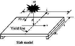
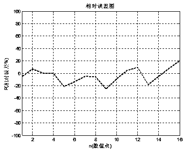

Image

  • Component surface explosion load distribution rule analysis method
  • Component surface explosion load distribution rule analysis method
  • Component surface explosion load distribution rule analysis method

Examples


Embodiment Construction

[0057] The present invention is described in conjunction with accompanying drawing and specific embodiment:

[0058] An analytical method for the distribution of explosive loads on the surface of a steel component, the specific steps of the analytical method are as follows:

[0059] 1) Firstly, calculate the peak pressure and forward impulse of the center of the blast surface; use the least squares curve fitting method to establish the fitting formula of the peak pressure of the regular reflection and the forward impulse; the fitting formula of the peak pressure of the regular reflection is:

[0060]

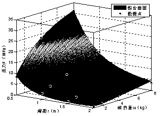
[0061] In the formula, P is the peak value of positive reflection overpressure, and the unit is MPa, r is the burst distance, the unit is m, Z is the proportional distance in m / kg 1 / 3 ; figure 2 The relationship between the peak pressure of the regular reflection, the charge and the detonation distance, and the relationship between the fitting surface and the numerical ...


PUM


Abstract

The invention belongs to the technical field of weapon damage assessment, and particularly relates to a method for analyzing the distribution law of explosion loads on the surface of a steel member. The component surface explosion load distribution rule analysis method comprises the following specific steps: firstly, calculating the positive reflection peak pressure and the positive impulse of thecenter of an explosion facing surface; establishing a fitting formula of the positive reflection peak pressure and the positive impulse by utilizing a least square curve fitting method; determining acomponent surface distribution function; determining explosion load parameters of any point on the surface of the component; and combining the explosion load parameters of the central point of the component, namely explosion load reflection pressure P and impulse I, and determining the explosion load parameters of any point by utilizing the normalized distribution function sum, namely, after theexplosion load parameters of the surface of the component are determined by utilizing the method, performing evaluation analysis on the damage of the component by utilizing the obtained explosion loadparameters. The method has the advantages that the effect in the near-explosion explosion environment can be quickly and reliably calculated, and the like.

Description

technical field [0001] The invention belongs to the technical field of weapon damage assessment, and in particular relates to an analysis method for the distribution rule of explosion load on the surface of steel components. Background technique [0002] How to determine the blast load on the structure surface is the key to structural damage assessment and response analysis. The usual method is to use the empirical formula established by the field explosion test data, but due to the safety and economic reasons of the test, the test data is very small, and most of the empirical formulas are only applicable to the infinite surface of the structure, and this assumption does not apply to a single structure with a finite width. Not applicable. If you continue to use this type of formula to predict the load on the surface of the structure, it will cause a large deviation, which will seriously affect the development of damage assessment. [0003] At present, most of the blast load...

Claims


Application Information

Patent Timeline
Patent Type & Authority Applications(China)
IPC IPC(8): G06F17/50
Inventor 汪维吴飚刘瑞朝何翔陈力黄家蓉杨建超王幸徐翔云
Owner INST OF DEFENSE ENG ACADEMY OF MILITARY SCI PLA CHINA
Learn More