Method and related device for automatic focusing of fiber end face based on neural network
An optical fiber end face, neural network technology, applied in neural learning methods, biological neural network models, neural architectures, etc., can solve the problems of poor generality of focusing methods, slow focusing speed, and low focusing accuracy, and achieve high-efficiency and high-precision automatic focusing, Time cost balance, anti-interference effect
- Summary
- Abstract
- Description
- Claims
- Application Information
AI Technical Summary
Problems solved by technology
Method used
Image
Examples
Embodiment 1
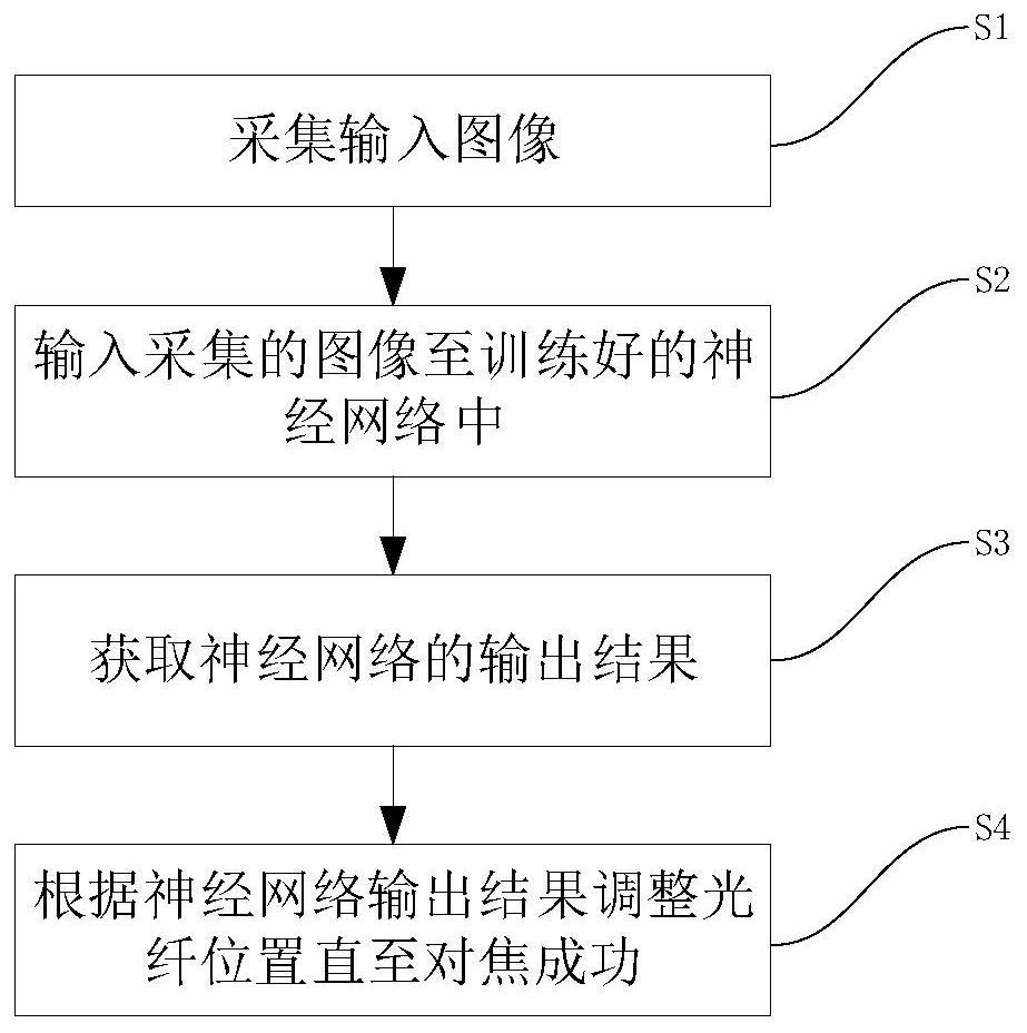
[0047] The present invention is based on a neural network algorithm to realize fast and accurate automatic focusing on the end face of an optical fiber. Embodiment 1 of the present invention provides an automatic focusing method on an optical fiber end face based on a neural network. figure 1 A flow chart of the implementation of a neural network-based automatic focusing method for an optical fiber end face provided by an embodiment of the present invention, as shown in figure 1 As shown, the method may include the following steps:
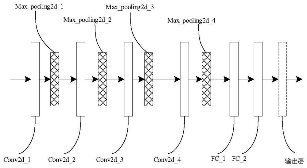
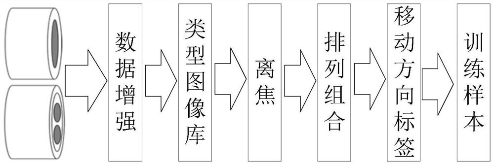
[0048] S1: Collect the input image, the input image includes two, specifically, first set the current position of the optical fiber as the initial position, collect the fiber end face image at the initial position as the first fiber end face image, and then press the axial direction with the preset step Moving the optical fiber clamp to the second position, and acquiring the end face image of the optical fiber at the second position as the second en...
Embodiment 2
[0103] like Figure 5 As shown, it is a structural block diagram of a neural network-based device for automatic focusing of an optical fiber end face in this embodiment, including:
[0104] The first acquisition device is used to acquire the first optical fiber end face image at the initial position after setting the current position of the optical fiber as the initial position;
[0105] The second collecting device is used to collect and obtain the second optical fiber end face image at the second position after moving the optical fiber clamp to the second position with preset steps;
[0106] The neural network output device is used to input the first optical fiber end face image and the second optical fiber end face image into the trained neural network according to the acquisition order, and obtain the output result of the neural network, and the output result is according to the definition change of the two input pictures The corresponding moving direction label generated...
Embodiment 3
[0109] like Image 6 As shown, it is a schematic structural diagram of a neural network-based fiber end-face automatic focusing device in this embodiment, including: a displacement platform, an optical fiber fixture, a numerical control module, a control device, an image acquisition device, and a ring power supply.
[0110] Among them, the optical fiber clamp is rigidly connected to the displacement platform for fixing the end face of the optical fiber. The displacement platform is a high-precision single-axis displacement platform, and the high-precision single-axis displacement platform is rigidly connected to the optical fiber clamp, which is used to quantitatively and accurately change the object distance.
[0111] The image acquisition device includes a microscopic system and a camera for collecting images of the end face of the optical fiber. The microscopic system is composed of a microscopic objective lens and a lens barrel, which can obtain a clear image of the end fac...
PUM
 Abstract
Description
Claims
Application Information
 - R&D
- Intellectual Property
- Life Sciences
- Materials
- Tech Scout
- Unparalleled Data Quality
- Higher Quality Content
- 60% Fewer Hallucinations
Browse by: Latest US Patents, China's latest patents, Technical Efficacy Thesaurus, Application Domain, Technology Topic, Popular Technical Reports.
© 2025 PatSnap. All rights reserved.Legal|Privacy policy|Modern Slavery Act Transparency Statement|Sitemap|About US| Contact US: help@patsnap.com


