Control device suitable for LED linear illumination

A technology for control devices and LED strips, applied in lighting devices, semiconductor lamps, electrical components, etc., can solve the problems of overheating and blackening of lamp beads, large and uneven temperature difference between head and tail, and large pressure drop, and achieve uniform brightness. Effect

Inactive Publication Date: 2019-06-25
珠海市宏科电子科技有限公司
View PDF0 Cites 1 Cited by
  • Summary
  • Abstract
  • Description
  • Claims
  • Application Information

AI Technical Summary

Problems solved by technology

[0003] 1. Uneven brightness at the head and tail: Due to the low working voltage, high working current, long distance and large line loss of LED line lights (flexible and hard light strips), the voltage difference between the head and the tail is large, because the lines generally adopt constant voltage working mode, Therefore, the phenomenon of uneven brightness at the head and tail directly occurs, which greatly affects the lighting effect and is currently the biggest pain point in the entire lighting industry.
[0004] 2. It is difficult to achieve long-distance seamless extension: it is precisely because of the above-mentioned problems caused by the large pressure drop that generally a single circuit is at most 5-10 meters long (12V5 meters, 24V10 meters), which increases the difficulty of construction and greatly affects the application effect
[0005] 3. It is difficult to realize centralized power supply: the traditional scheme must be equipped with an electrical appliance for 5-10 meters, which leads to high product cost, high construction cost, and high maintenance cost
[0006] 4. Hidden dangers in quality: Due to the large voltage drop and line loss of the traditional solution, the voltage at the power supply head is high and the loop current is large and the heat is serious. The terminal voltage is low and the loop current is small and heat is small. The lamp bead is overheated and blackened, and the product quality is poor

Method used


Image

  • Control device suitable for LED linear illumination
  • Control device suitable for LED linear illumination
  • Control device suitable for LED linear illumination

Examples


Embodiment Construction

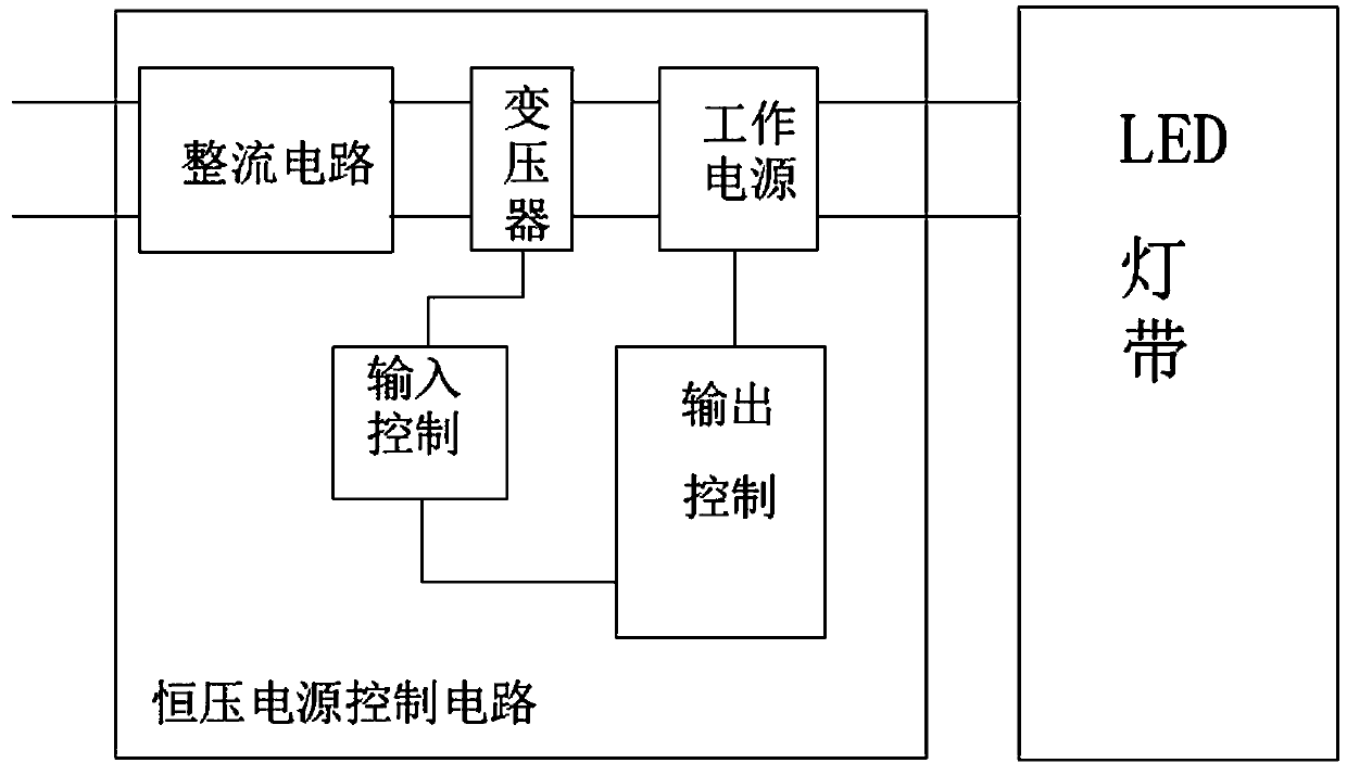
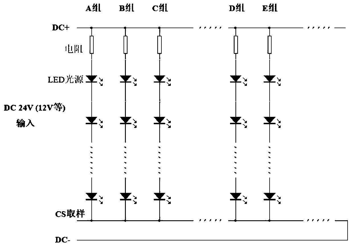
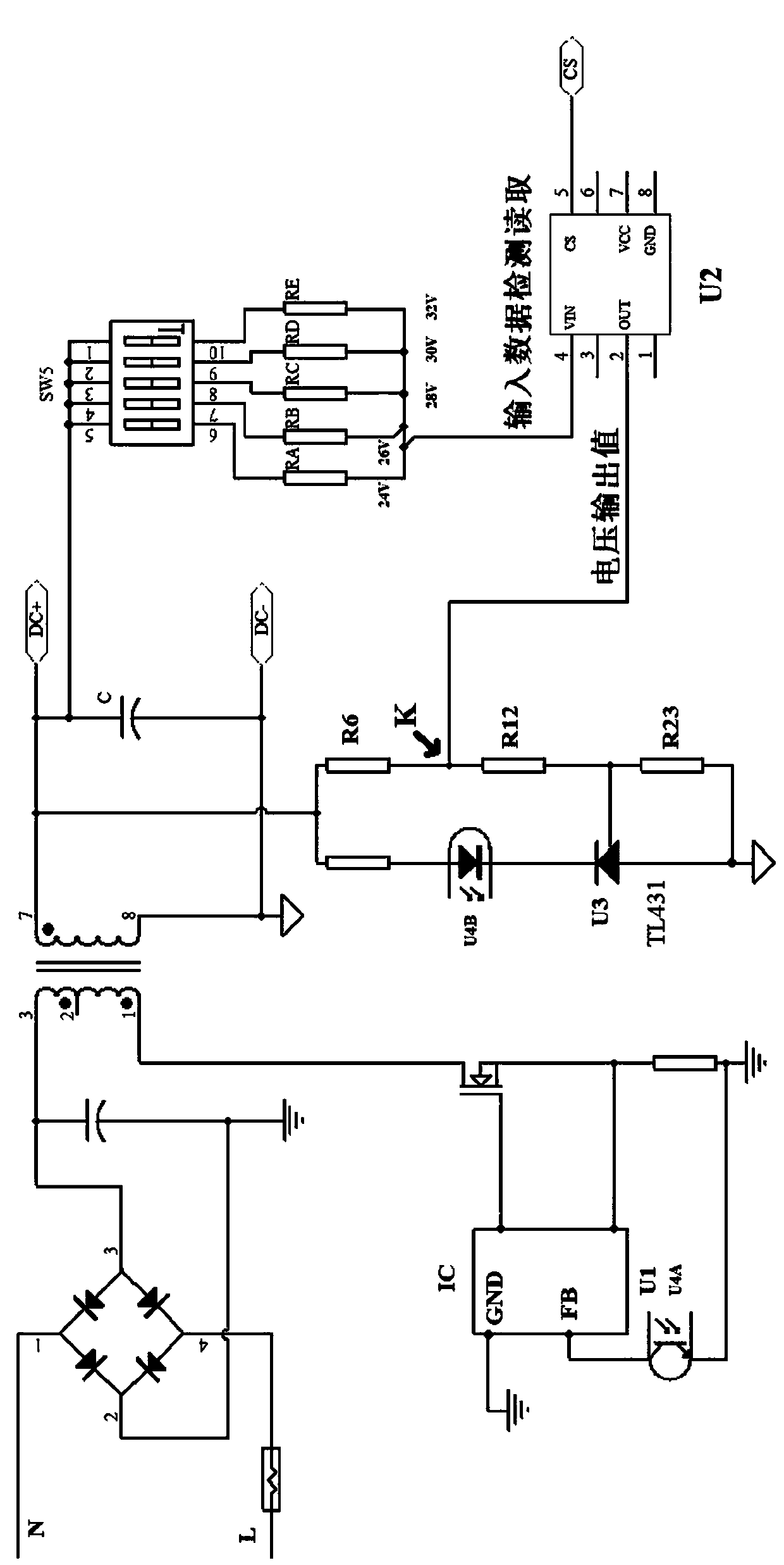
[0017] Such as Figure 1 to Figure 3 As shown, the present invention includes an LED light strip and a constant voltage power supply control circuit, the LED light strip is electrically connected to the constant voltage power supply control circuit, and the LED light strip includes a lamp composed of a resistor connected in series with an LED light The light strip composed of the resistor and the LED lamp in series can be connected in parallel in multiple groups. The constant voltage power supply control circuit includes a rectifier bridge circuit, a fuse, an input filter capacitor, a transformer, an output filter capacitor, a power input control circuit, Power supply output control circuit, the input terminal of the rectifier bridge circuit is connected in series with the L terminal and the N terminal of the power supply, the output terminal of the rectifier bridge circuit is connected in parallel with the input filter capacitor, and the rectifier bridge circuit One end of th...


PUM


Abstract

The invention discloses and provides a control device for LED linear illumination, wherein the control device is uniform in brightness, has the functions of automatic collection, detection and judgment and can perform automatic control. The control device comprises an LED lamp strip and a constant-voltage power supply control circuit which are connected with each other. The LED lamp strip comprises lamp strips formed by the series connection of resistors and LED lamps, wherein a plurality of groups of lamp strips can be connected in parallel. The constant-voltage power supply control circuit comprises a rectifier bridge circuit, a fuse wire, an input filter capacitor, a transformer, an output filter capacitor, a power supply input control circuit and a power supply output control circuit.The input end of the rectifier bridge circuit is connected with the L end and the N end of a power supply connected with the fuse wire in series, and the transformer outputs the working power supplies: DC+ and DC-. The power supply input control circuit and the power supply output control circuit are linked to work to control the constant-voltage output of the working power supplies.

Description

technical field [0001] The patent of the present invention relates to the field of LED electrical lighting, especially to LED linear lighting, including LED flexible light strips, LED hard light strips, LED line lights, and LED magnetic suction linear lighting systems. Background technique [0002] With the wide application of LED technology, LED linear lighting has been widely used due to its convenient shape, low glare, continuous light emission and easy embedding into decoration spaces. But existing technical scheme has following defective owing to technical problem: [0003] 1. Uneven brightness at the head and tail: Due to the low working voltage, high working current, long distance and large line loss of LED line lights (flexible and hard light strips), the voltage difference between the head and the tail is large, because the lines generally adopt constant voltage working mode, Therefore, the phenomenon of uneven brightness at the head and tail directly occurs, which...

Claims


Application Information

Patent Timeline
Patent Type & Authority Applications(China)
IPC IPC(8): H05B33/08H05B44/00
CPCY02B20/30
Inventor 周小宏王岩
Owner 珠海市宏科电子科技有限公司
Why Eureka
Try Eureka