
Eye movement interpretation method and system

An eye movement, right eye technology, used in eye testing equipment, medical science, sensors, etc.

Inactive Publication Date: 2019-06-28
BMC MEDICAL
View PDF4 Cites 3 Cited by
  • Summary
  • Abstract
  • Description
  • Claims
  • Application Information

AI Technical Summary

Problems solved by technology

[0004] The purpose of the present invention is to provide an eye movement interpretation method and system for solving the problems of automatic interpretation of eye movement events and improving the accuracy of interpretation

Method used


Image

  • Eye movement interpretation method and system
  • Eye movement interpretation method and system
  • Eye movement interpretation method and system

Examples


Embodiment Construction

[0022] The specific implementation manners of the embodiments of the present invention will be described in detail below in conjunction with the accompanying drawings. It should be understood that the specific implementation manners described here are only used to illustrate and explain the embodiments of the present invention, and are not intended to limit the embodiments of the present invention.

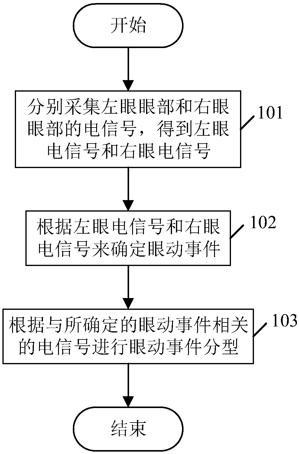
[0023] figure 1 It is a flow chart of the eye movement interpretation method provided by the embodiment of the present invention, such as figure 1 As shown, the process includes:

[0024] In step 101, the electrical signals of the left eye and the right eye are respectively collected to obtain the left eye electrical signal and the right eye electrical signal. The left eye electrical signal and the right eye electrical signal here are both voltage signals, and those skilled in the art should understand that after the left eye electrical signal and the right eye electrical signal...


PUM


Abstract

The invention provides an eye movement interpretation method and system, and belongs to the technical field of eye movement interpretation. The eye movement interpretation method comprises the steps that electrical signals of a left eye and a right eye are collected respectively, and left eye electrical signals and right eye electrical signals are obtained; eye movement events are determined according to the left eye electrical signals and the right eye electrical signals; the eye movement events are classified according to the electrical signals related to the determined eye movement events.Accordingly, by determining the eye movement events according to the collected left eye electrical signals and right eye electrical signals and classifying the eye movement events according to the electrical signals related to the determined eye movement events, not only is automatic interpretation of the eye movement events achieved, but also the accuracy of interpretation of the eye movement events is greatly improved.

Description

technical field [0001] The invention relates to eye movement interpretation technology, in particular to an eye movement interpretation method and system. Background technique [0002] Because there is a potential difference between the cornea and the retina, the potential of the skin around the eyes will change accordingly with the rotation of the eyeball, and the potential difference between the retina and the cornea will change with the rotation of the eyeball. This potential signal is the oculoelectric signal . Due to the different sleep stages of people during sleep, the performance of oculoelectric signal is also different. REM (Rapid Eyes Movement) stage is often accompanied by rapid eye movement, awake eyes closed and sleep N1 stage often appear slow eye movement. [0003] Oculoelectric waves are combined when determining sleep stages, and eye waves need to be interpreted manually according to standards. This not only requires high professional requirements for det...

Claims


Application Information

Patent Timeline
Patent Type & Authority Applications(China)
IPC IPC(8): A61B3/113A61B5/0496
Inventor 李杰侯丙营庄志
Owner BMC MEDICAL
Learn More