Cooling liquid control device

A control device and coolant technology, which is applied in the direction of manufacturing tools, metal processing machinery parts, maintenance and safety accessories, etc., can solve the problem that there is no way to meet the coolant injection, and achieve the effect of increasing the discharge speed and improving the machining accuracy

Pending Publication Date: 2019-06-28
上海历焱自动化设备有限公司
View PDF0 Cites 0 Cited by
  • Summary
  • Abstract
  • Description
  • Claims
  • Application Information

AI Technical Summary

Problems solved by technology

[0003] At present, in the field of metal cutting processing, the control of coolant (also known as cutting fluid) mostly uses bendable hoses to control the direction of coolant spray, which requires manual adjustment. Ways to meet the need for coolant to be sprayed at the tip of the tool all the time

Method used


Image

  • Cooling liquid control device
  • Cooling liquid control device
  • Cooling liquid control device

Examples


Embodiment 1

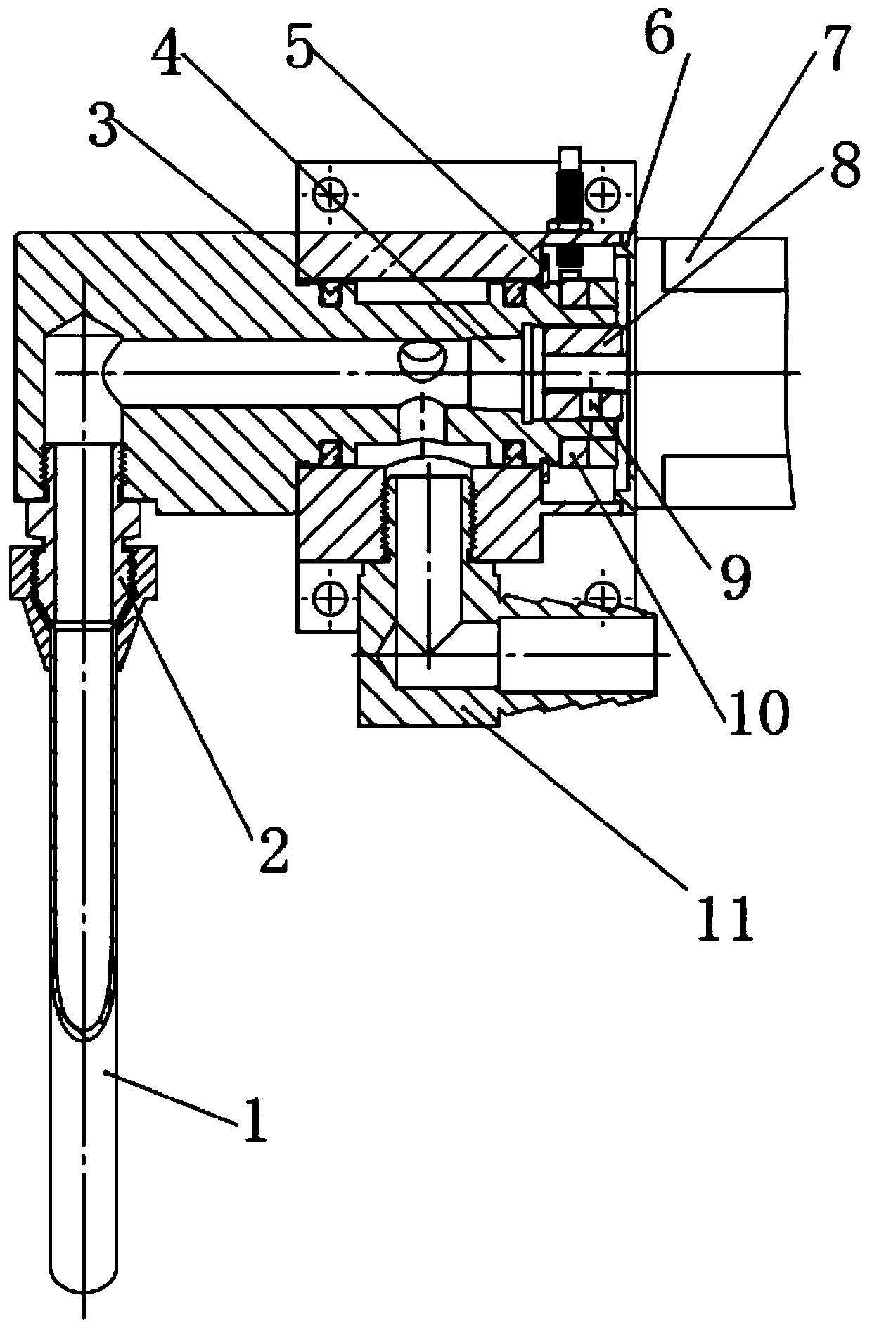
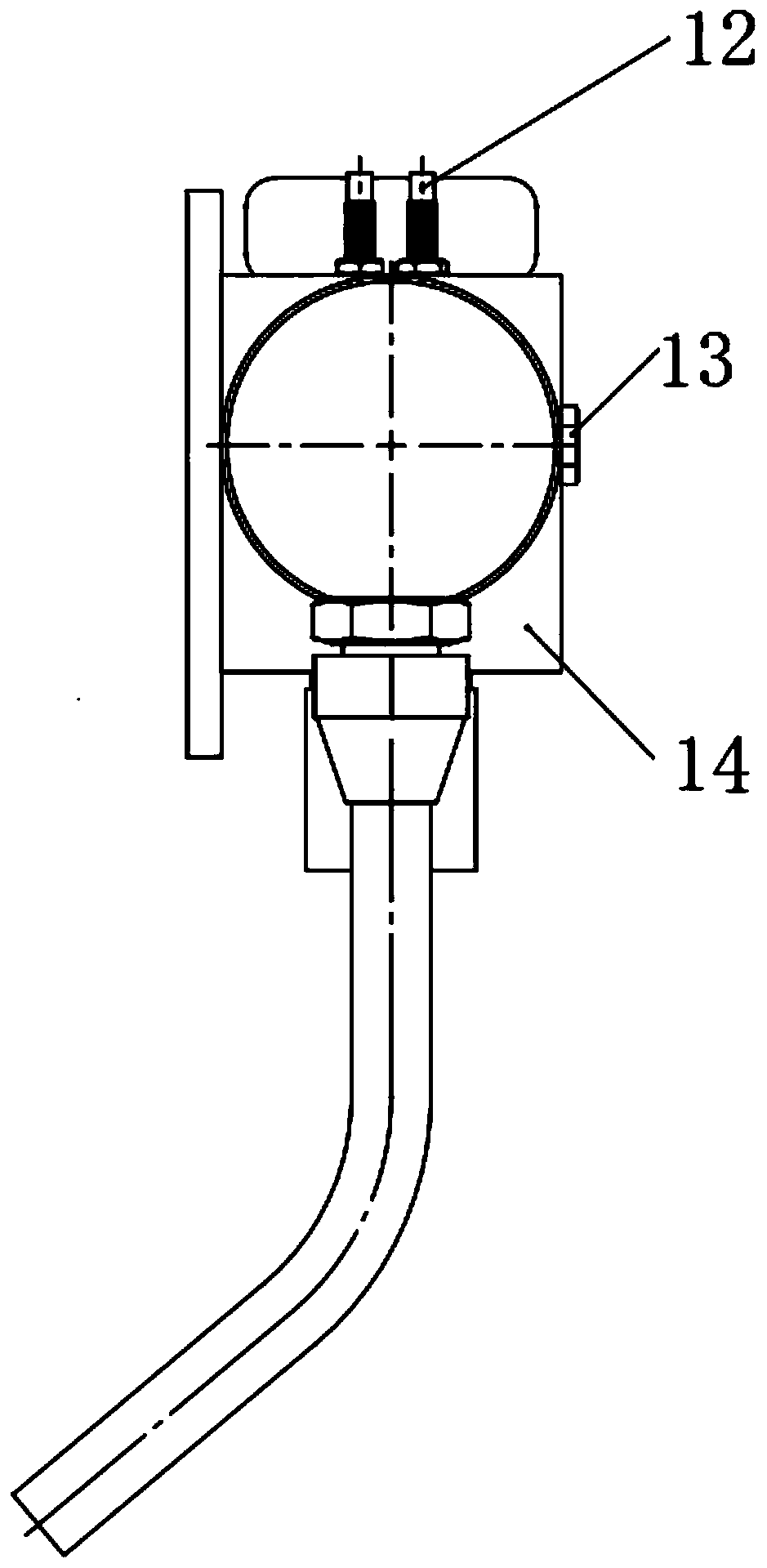
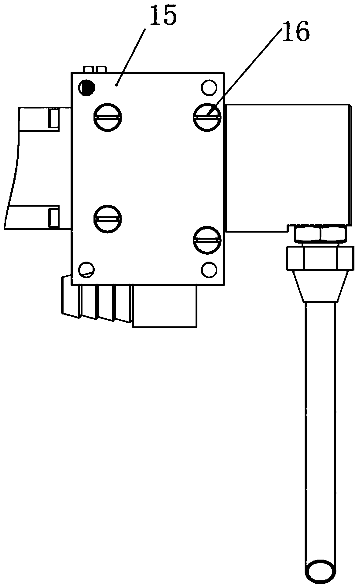
[0025] see Figures 1 to 5 , In the embodiment of the present invention, a cooling liquid control device includes a valve body 14, a valve core 17 and a control motor 7, the lower side of the valve core 17 is connected with a pipe 1 through a straight pipe joint 2, and the valve body 14 A two-way piston seal 3 is arranged between the valve core 17 and the valve body 14. A positioning plate 6 is arranged at the right end of the valve body 14. The valve body 14 is connected to the control motor 7 through the positioning plate 6, and a bump block is arranged between the positioning plate 6 and the valve body 14. 10. A proximity switch 12 is provided on the outside of the valve body 14, a plug 4 is provided in the valve core 17, and a rubber hose square pipe joint 11 is also provided on the lower side of the valve core 17. A shaft retaining ring 5 is provided, and a transition sleeve 8 is provided at the inner right end of the valve core 17 .

[0026] The straight pipe joint 2 is...

Embodiment 2

[0029] On the basis of the first embodiment, the bumper 10 is installed by a set screw with a conical end, and the transition sleeve 8 is connected with the valve core 17 by a set screw 9 with a flat end. It is convenient to install and remove the bumper 10 and the transition sleeve 8 .


PUM


Abstract

The invention relates to the technical field of technical machining, in particular to a cooling liquid control device. The cooling liquid control device comprises a valve body, a valve element and a control motor. The lower side of the valve element is connected with a pipe through a straight pipe joint. A bidirectional piston seal is arranged between the valve body and the valve element. A locating plate is arranged at the right end of the valve body. The valve body is connected with the control motor through the locating plate. A bumping block is arranged between the locating plate and the valve body. A proximity switch is arranged on the outer side of the valve body. A plug is arranged in the valve element. A rubber hose angle square pipe joint is further arranged on the lower side of the valve element. A shaft check ring is arranged between the bumping block and the valve body. A transition sleeve is arranged at the right end in the valve element. Through structural arrangement ofthe device, the cooling liquid injection angle can be automatically adjusted according to tool data given by an upper computer, and therefore the cooling liquid injection direction is controlled, thedischarging speed of waste scraps in the tool cutting process is increased, and the product machining precision is improved.

Description

technical field [0001] The invention relates to the technical field of metal processing, in particular to a cooling liquid control device. Background technique [0002] Metal processing refers to the production activities in which humans process materials with metallic properties composed of metallic elements or mainly composed of metallic elements. The progress of human society is closely related to the processing and application of metal materials. Brass was smelted more than 6,000 years ago, simple bronze tools were made more than 4,000 years ago, and meteorite iron was used more than 3,000 years ago. Weapons, China has been smelting pig iron in the Spring and Autumn Period more than 2,500 years ago, more than 1,800 years earlier than Europe. In the 18th century, the development of the iron and steel industry became an important content and material basis for the Industrial Revolution. [0003] At present, in the field of metal cutting processing, the control of coolant...

Claims


Application Information

Patent Timeline
IPC IPC(8): B23Q11/10B23Q11/00
Inventor 吴荣曹延娜
Owner 上海历焱自动化设备有限公司
Why Eureka
Try Eureka