Clamping mechanism for mechanical deformation machining

A clamping mechanism and mechanical deformation technology, which is applied in the field of clamping mechanisms for mechanical deformation processing, can solve the problems of inconvenient conversion of angles, clamping of mechanical parts deformation processing, and inconvenience of different types, so as to improve the stable clamping effect, Increase the strength of clamping and facilitate the effect of stable clamping

Active Publication Date: 2019-06-28
JILIN TEACHERS INST OF ENG & TECH
View PDF6 Cites 3 Cited by
  • Summary
  • Abstract
  • Description
  • Claims
  • Application Information

AI Technical Summary

Problems solved by technology

[0003] At present, when the existing mechanical clamping mechanism deforms the workpiece, most of them are inconvenient to adjust the angle, and it is inconvenient to change the angle. It requires workers to manually turn over the mechanical product. The degree of automation is low, and there is more waste during work. time, resulting in lower working efficiency of its mechanical deformation processing, and the existing clamping mechanism is not convenient for deformation processing and clamping of different types of mechanical parts, resulting in the need to replace different pressure plates when processing different workpieces. In the process of disassembly and assembly, more time is wasted further, and the clamping stability of some existing mechanical clamping mechanisms is poor. Therefore, we provide a clamping mechanism for mechanical deformation processing to solve this problem. question

Method used


Image

  • Clamping mechanism for mechanical deformation machining
  • Clamping mechanism for mechanical deformation machining
  • Clamping mechanism for mechanical deformation machining

Examples


Embodiment Construction

[0024] The following will clearly and completely describe the technical solutions in the embodiments of the present invention with reference to the accompanying drawings in the embodiments of the present invention. Obviously, the described embodiments are only some, not all, embodiments of the present invention.

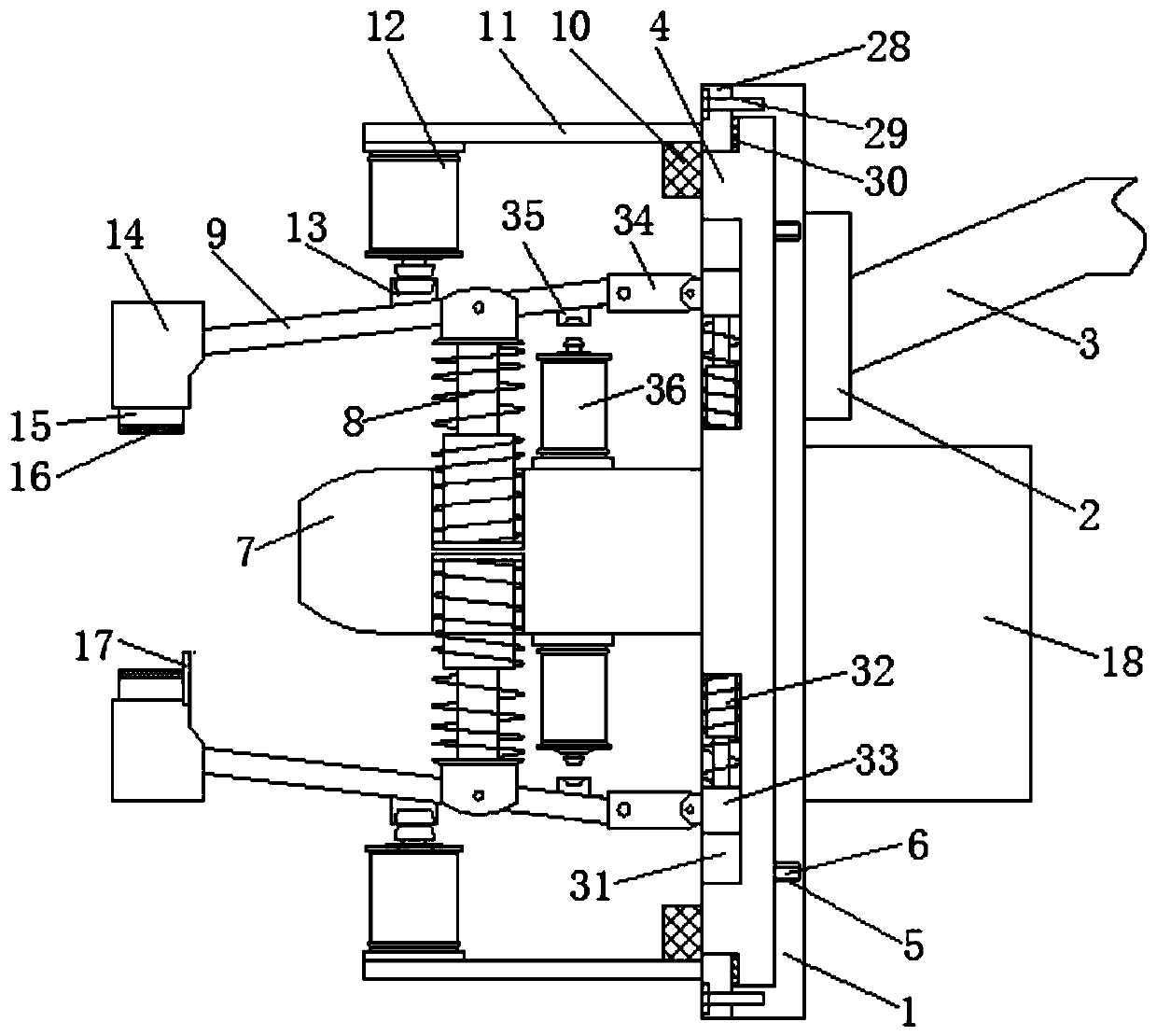
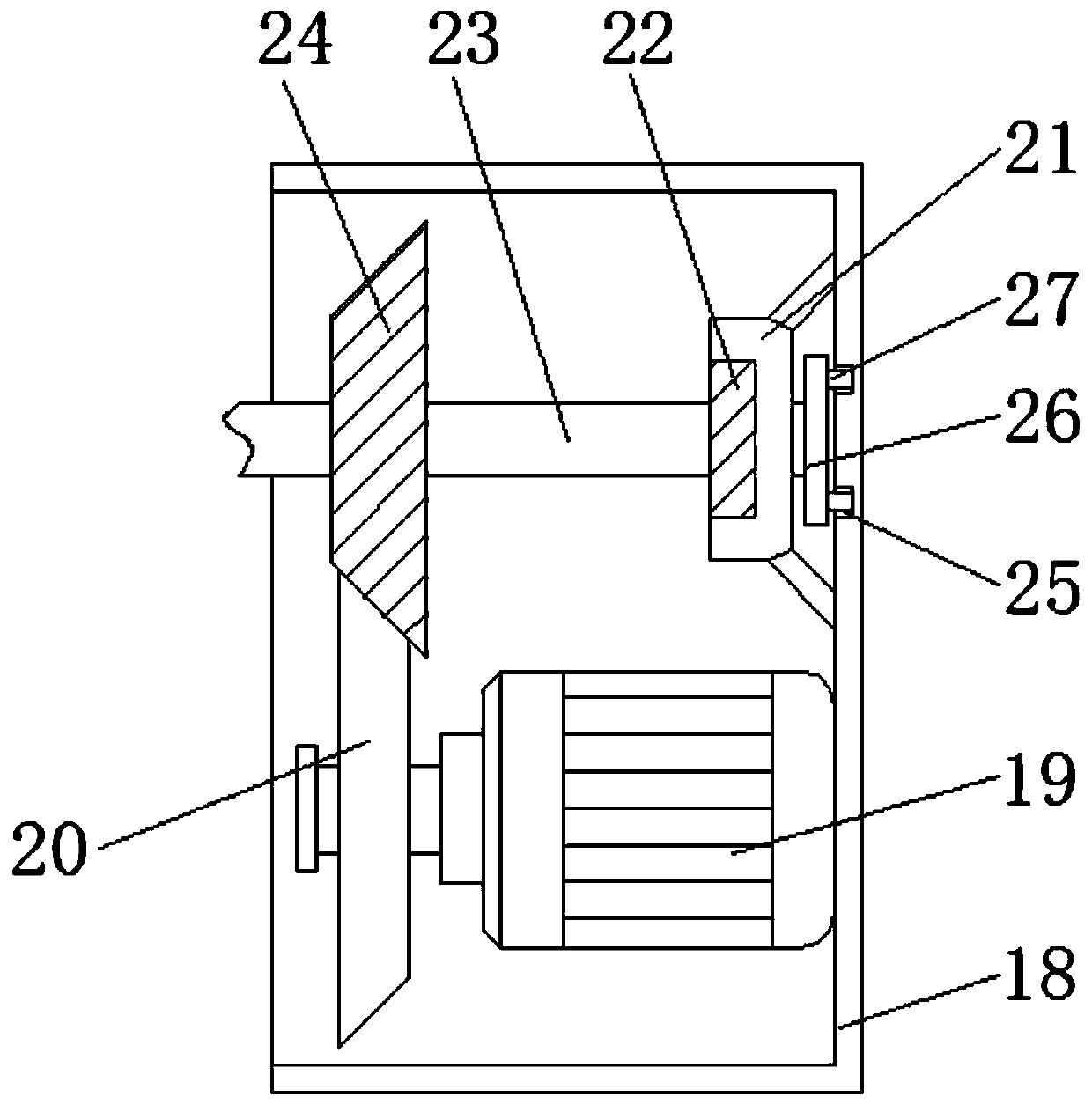
[0025] refer to Figure 1-5 , a clamping mechanism for mechanical deformation processing, including a mounting plate 1, the right side of the mounting plate 1 is connected with a support rod 3 through a first fixed block 2, a turntable 4 is provided on the left side of the mounting plate 1, and the right side of the mounting plate 1 The side is connected with the first fixed cover 18, the inner cavity of the first fixed cover 18 is equipped with a motor 19, the left side of the motor 19 is connected with the first bevel gear 20, and the inner cavity right side of the first fixed cover 18 is connected with a bearing seat 21 The inner cavity of the bearing seat 21 is p...


PUM


Abstract

The invention relates to the technical field of mechanical clamping, in particular to a clamping mechanism for mechanical deformation machining. The clamping mechanism for mechanical deformation machining comprises a mounting plate, wherein the right side of the mounting plate is connected with a supporting rod through a first fixing block; the left side of the mounting plate is provided with a turntable; the left side of the mounting plate is provided with a first annular groove; the right side of the turntable is symmetrically provided with first sliding blocks matched with the turntable; the left side of the turntable is connected with a first fixing plate; the two ends of the first fixing plate are provided with grooves; a first spring rod is arranged in the inner cavity of each groove; and one ends, away from the first spring rods, of the groovesare movably connected with clamping arms through connecting pieces.The clamping mechanism is novel in structural design, the clamping force of the clamping mechanism is effectively enhanced, the stable clamping effect of the clamping mechanism is favorably improved, machines of different forms are conveniently machined, the working time is effectively reduced, the working efficiency is conveniently improved, and moreover, a clamped mechanical part is conveniently overturned and adjusted, and is convenient to use.

Description

technical field [0001] The invention relates to the technical field of mechanical clamping, in particular to a clamping mechanism for mechanical deformation processing. Background technique [0002] The clamping mechanism is a mechanical mechanism used by mechanical equipment in the manufacturing industry to fix the processing object. In order to prevent the workpiece from moving during processing, causing the processing position to shift and resulting in defective products, the workpiece needs to be fixed before machining Clamping, so the clamping mechanism will be used to clamp the workpiece, and the clamping device will clamp and fix the workpiece, which is convenient for workers to process the workpiece. [0003] At present, when the existing mechanical clamping mechanism deforms the workpiece, most of them are inconvenient to adjust the angle, and it is inconvenient to change the angle. It requires workers to manually turn over the mechanical product. The degree of auto...

Claims


Application Information

Patent Timeline
Patent Type & Authority Applications(China)
IPC IPC(8): B65G47/90B65G47/248
Inventor 崔亚新崔雅嵩
Owner JILIN TEACHERS INST OF ENG & TECH
Why Eureka
Try Eureka