Roller anti-loose structure

A rolling wheel and anti-loosening technology, which is applied in the direction of shafts and bearings, can solve problems such as relative displacement, machine failure to operate normally, slipping, etc.

Pending Publication Date: 2019-06-28
北京清大天达光电科技股份有限公司
View PDF15 Cites 0 Cited by
  • Summary
  • Abstract
  • Description
  • Claims
  • Application Information

AI Technical Summary

Problems solved by technology

In this process, there is relative sliding between the roller and the inner sleeve, and as the working time increases, the wear of the inner sleeve and the roller is gradually serious, and relative displacement is particularly prone to occur, resulting in slipping and making the machine unable to operate normally.

Method used


Image

  • Roller anti-loose structure
  • Roller anti-loose structure
  • Roller anti-loose structure

Examples


Embodiment Construction

[0023] The present invention will be described in detail below in conjunction with the accompanying drawings and specific embodiments, wherein the schematic embodiments and descriptions are only used to explain the present invention, but are not intended to limit the present invention.

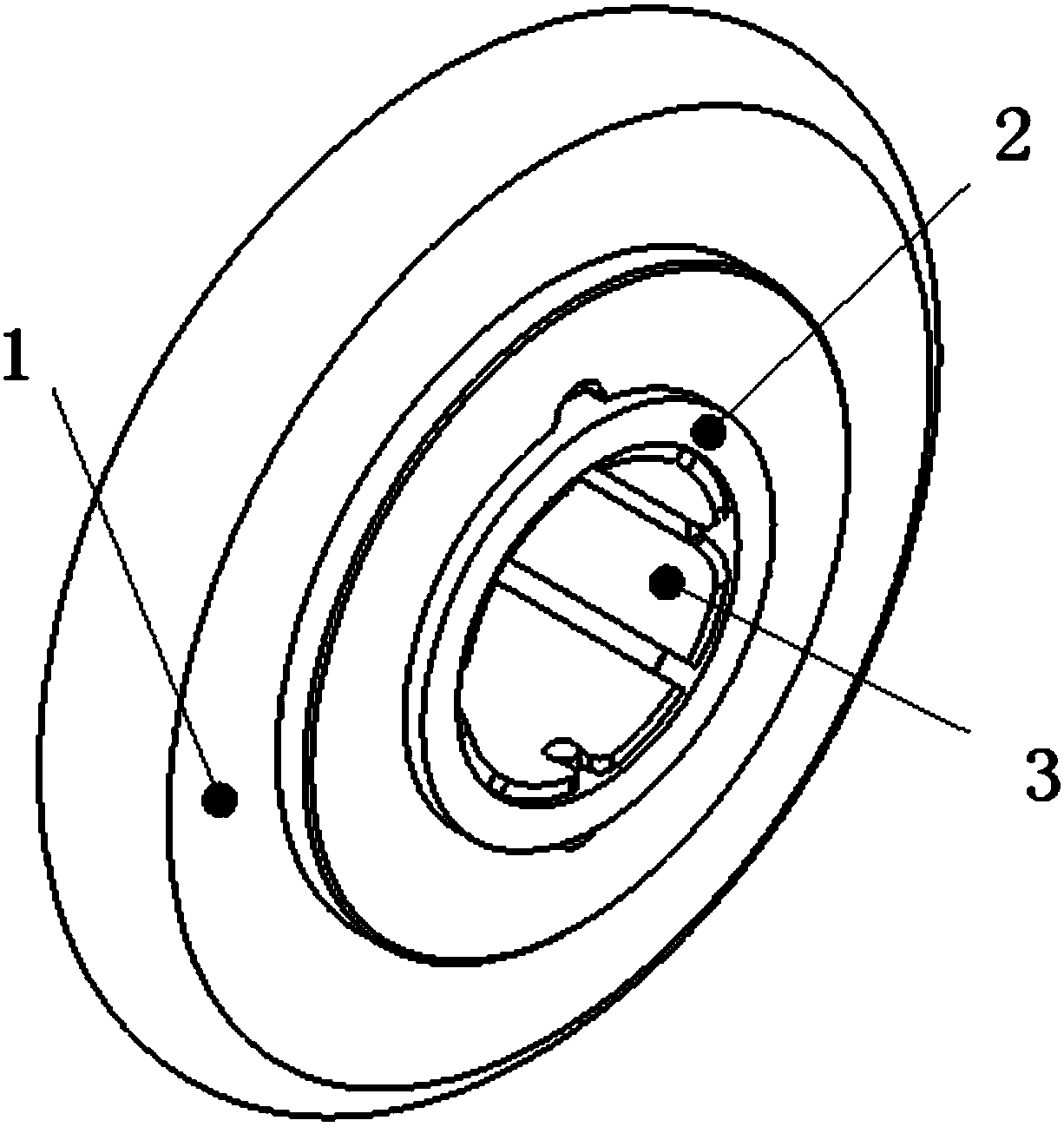
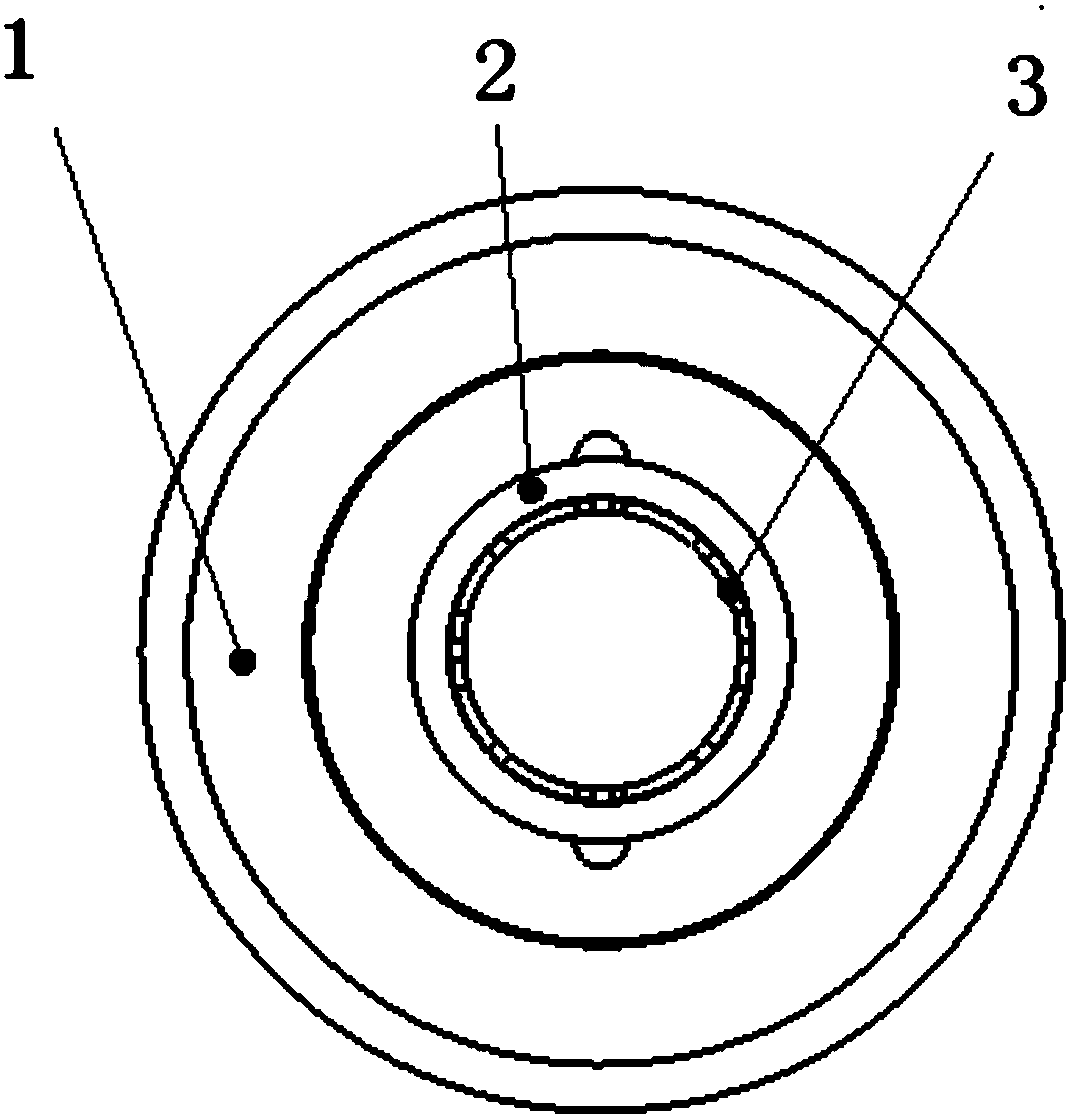
[0024] Such as Figure 1-2 As shown, a roller anti-loosening structure includes a roller 1, a locking inner sleeve 2 and a clamping inner sleeve 3, and the roller 1, the locking inner sleeve 2 and the clamping inner sleeve 3 are all made of plastic; The inner ring of the roller 1 is matched with the outer ring of the locking inner sleeve 2; the inner ring of the locking inner sleeve 2 is matched with the inner ring of the roller 1 and the outer ring of the clamping inner sleeve 3; the described The inner ring of clamping inner sleeve 3 is connected with the shaft, and its outer ring cooperates with the inner ring of locking inner sleeve 2 . Said roller 1 is provided with a mating end face, sa...


PUM


Abstract

The invention relates to a roller anti-loose structure. The roller anti-loose structure comprises a roller, a locking inner sleeve and a clamping inner sleeve, the inner ring of the roller is matchedwith the outer ring of the locking inner sleeve; the locking inner sleeve is matched with the inner ring of the roller and the outer ring of the clamping inner sleeve; the inner ring of the clamping inner sleeve is connected with a shaft, and the outer ring of the clamping inner sleeve is matched with the inner ring of the locking inner sleeve. The roller anti-loose structure is simple in structure, reasonable in design and convenient to use, the original interference fit of a transmission device is changed to be fixedly connected, the abrasion of the roller and the inner sleeve is effectivelyreduced, the service life of the transmission device is prolonged, and the economic cost of equipment is reduced; in addition, the rotating speed of the roller can be well guaranteed through the roller anti-loose structure.

Description

【Technical field】 [0001] The invention relates to a roller anti-loosening structure, which belongs to the technical fields of microelectronics, semiconductors and flat panel displays, and in particular to a non-slip assembly of a shaft and a roller, which can be used for material transportation, torque transmission or movement of certain equipment. 【Background technique】 [0002] In the assembly of the shaft and the roller, a large amount of interference fit is generally used, that is, the diameter of the outer ring of the inner sleeve is slightly larger than the diameter of the inner ring of the roller, and the basic relative position of the shaft and the roller can be realized through strong assembly. Thereby, the torque transmission between the shaft and the roller is achieved, and the rotation of the roller is realized. Usually such an assembly method relies on the internal force between the inner sleeve and the roller to achieve relative stability of the position, and t...

Claims


Application Information

Patent Timeline
Patent Type & Authority Applications(China)
IPC IPC(8): F16C13/00
Inventor 孟月王秋海赵双侠刘海溪
Owner 北京清大天达光电科技股份有限公司
Why Eureka
Try Eureka