
Novel projection display device for computer network engineering

A technology of computer network and projection display, which is applied in the direction of mechanical equipment, supporting machines, machines/stands, etc., which can solve the problems that the projection angle of the projection screen cannot be adjusted, and the projector cannot be adjusted, so as to achieve simple structure, easy movement, and convenient angle Adjustment effect

Inactive Publication Date: 2019-06-28
西安龙之梦网络信息有限公司
View PDF1 Cites 0 Cited by
  • Summary
  • Abstract
  • Description
  • Claims
  • Application Information

AI Technical Summary

Problems solved by technology

[0002] In the past few years, traditional home appliance companies have launched various intelligent home appliances, such as Internet TVs, Internet set-top boxes, smart washing machines, and smart refrigerators. Traditional home appliances and the Internet have begun to integrate gradually. In the future, electrical appliances and the Internet will combine to form network equipment. The terminal will be the development trend of home appliances. In modern home projection display equipment, it is mainly traditional projection. The traditional projection equipment is mostly a teaching projector. , the authorized notification number is CN203827445U discloses a ceiling-mounted projection display device, including a ceiling-mounted board, a projection function box and a decorative housing, the ceiling-mounted board is connected to the ceiling through a threaded hole provided thereon, and the projection The functional box is connected to the ceiling plate, the decorative casing is connected to the projection functional box, and the decorative casing is provided with a card slot connected with the projection functional box in a buckle manner, but the existing ceiling projection display device cannot Adjusting the position of the projector leads to the problem that the projection screen cannot be adjusted to the projection angle. Therefore, we propose a new type of projection display device for computer network engineering to solve the above problems.

Method used


Image

  • Novel projection display device for computer network engineering
  • Novel projection display device for computer network engineering

Examples


Embodiment Construction

[0018] The following will clearly and completely describe the technical solutions in the embodiments of the present invention with reference to the accompanying drawings in the embodiments of the present invention. Obviously, the described embodiments are only some, not all, embodiments of the present invention.

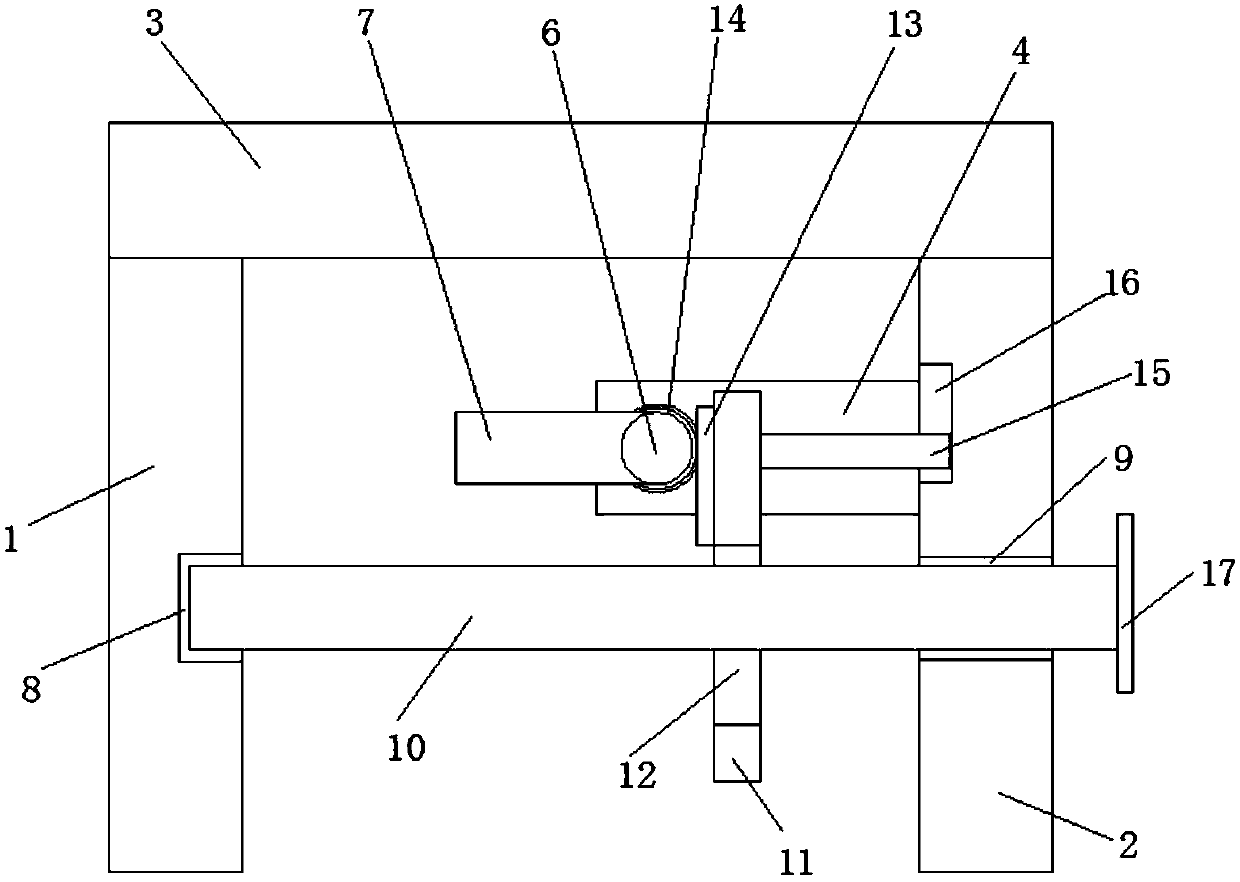
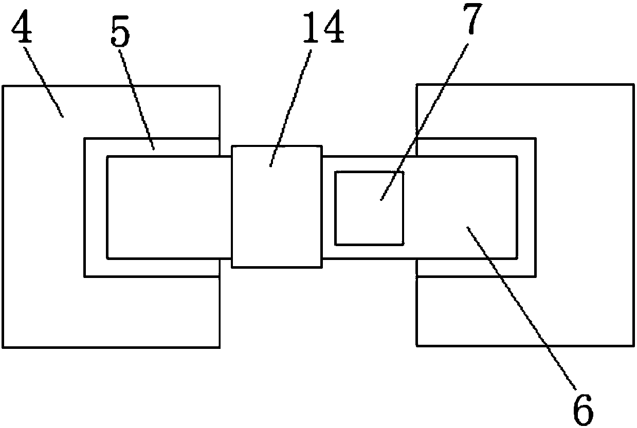
[0019] refer to Figure 1-2 , a novel projection display device for computer network engineering, comprising a first vertical board 1 and a second vertical board 2 positioned on one side of the first vertical board 1, the first vertical board 1 and the second vertical board 2 The top of the top is welded with the same top plate 3, and the side of the second vertical plate 2 close to the first vertical plate 1 is welded with two symmetrically arranged fixed plates 4, and the sides of the two fixed plates 4 that are close to each other are provided with The first rotating slot 5, and the same first rotating shaft 6 is installed in rotation in the two first rotating slo...


PUM


Abstract

The invention discloses a novel projection display device for computer network engineering. The device comprises a first vertical plate, and a second vertical plate which is positioned at one side ofthe first vertical plat, wherein a top plate is welded to the top parts of the first vertical plate and the second vertical plate; two symmetric fixing plates are welded to one side, close to the first vertical plate, of the second vertical plate; first rotating grooves are formed in the sides which are close to other of the two fixing plates; a first rotating shaft is rotatably mounted in the tworotating grooves; a projector is fixedly mounted at one side, close to the first vertical plate, of the first rotating shaft; and a second rotating groove and a rotating hole are correspondingly formed in the sides which are close to each other of the first vertical plate and the second vertical plate. The device is simple in structure, convenient to mount, economic and practical; a moving plateis convenient to move through the fixing plates and a second rotating shaft; in addition, a rack and a connecting plate are arranged, so that the angle of the projector can be adjusted.

Description

technical field [0001] The invention relates to the technical field of projection display equipment, in particular to a novel projection display equipment for computer network engineering. Background technique [0002] In the past few years, traditional home appliance companies have launched various intelligent home appliances, such as Internet TVs, Internet set-top boxes, smart washing machines, and smart refrigerators. Traditional home appliances and the Internet have begun to integrate gradually. In the future, electrical appliances and the Internet will combine to form network equipment. The terminal will be the development trend of home appliances. In modern home projection display equipment, it is mainly traditional projection. The traditional projection equipment is mostly a teaching projector. , the authorized notification number is CN203827445U discloses a ceiling-mounted projection display device, including a ceiling-mounted board, a projection function box and a d...

Claims


Application Information

Patent Timeline
IPC IPC(8): F16M11/06F16M11/18G03B21/54
Inventor 王朝霞
Owner 西安龙之梦网络信息有限公司
Features
  • Generate Ideas
  • Intellectual Property
  • Life Sciences
  • Materials
  • Tech Scout
  • Unparalleled Data Quality
  • Higher Quality Content
  • 60% Fewer Hallucinations
Learn More