Cooling and dehumidifying power cabinet based on semiconductor chilling plate

A technology of cooling, dehumidification, and refrigerating sheets, which is applied in the substation/distribution device casing, substation/switching device cooling/ventilation, etc., which can solve the problems of not easy to dissipate heat, electrical components, corrosion of power equipment, large space occupation, etc., to achieve Enhance cooling effect, reduce loss, and occupy less space

Active Publication Date: 2019-06-28
国网江苏省电力有限公司灌南县供电分公司 +1
View PDF10 Cites 4 Cited by
  • Summary
  • Abstract
  • Description
  • Claims
  • Application Information

AI Technical Summary

Problems solved by technology

[0002] As an important part of the power system, the power cabinet plays a very important role in the transmission process of the power grid. The normal operation of the electrical components in the power cabinet is an important guarantee for the normal transmission of the power grid. However, the electrical components inside the power cabinet are in A lot of heat will be generated when working for a long time, especially in summer, due to the small space inside the power cabinet, the heat inside the power cabinet is not easy to dissipate, and the electrical components inside the power cabinet will cause accidents due to aging or short circuit. , In the high temperature and rainy season, the air humidity is high, which will cause condensation inside the power cabinet. Condensation will cause corrosion of power equipment, short circuit and power outage accidents, causing great losses
[0003] When the power cabinet is in normal operation, it only needs a normal temperature, and it does not need to be too low. If the air conditioner is used to cool down, the air conditioner is large in size and takes up a lot of space, so it is very inconvenient to move

Method used


Image

  • Cooling and dehumidifying power cabinet based on semiconductor chilling plate
  • Cooling and dehumidifying power cabinet based on semiconductor chilling plate
  • Cooling and dehumidifying power cabinet based on semiconductor chilling plate

Examples


Embodiment

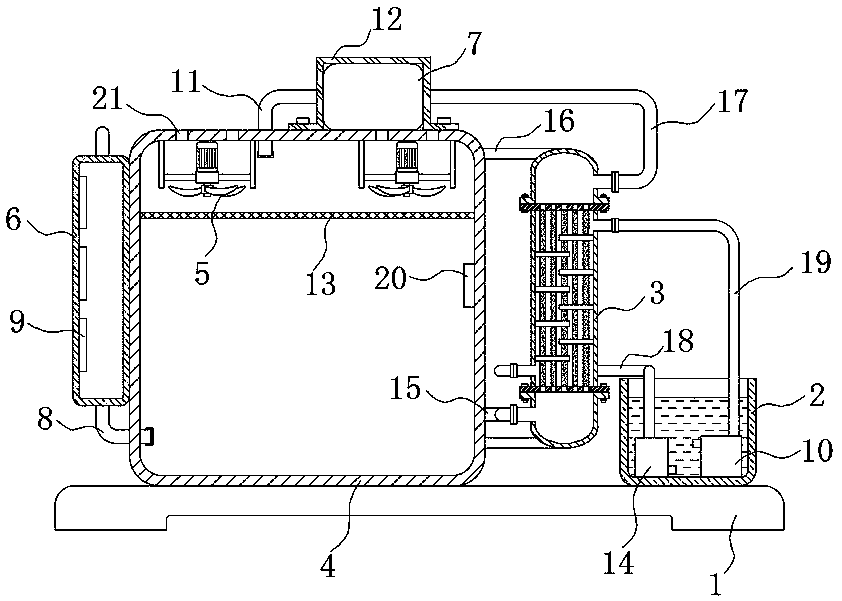
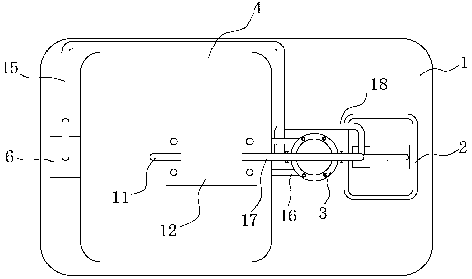
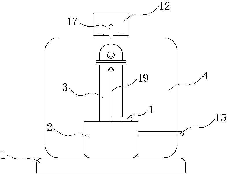
[0038] refer to Figure 1-6 , a cooling and dehumidification power cabinet based on semiconductor refrigeration chips, comprising a base 1, a cabinet body 4 and a water tank 2 are fixedly installed on the upper surface of the base 1.

[0039] A cooling mechanism 3 is fixedly installed on one side wall of the cabinet body 4, and a plurality of connecting rods 16 are symmetrically welded on the outer wall of the cabinet body 4, and the cooling mechanism 3 is installed on the plurality of connecting rods 16, and the cooling mechanism 3 includes cooling A cylinder 301, the two ends of the cooling cylinder 301 are evenly provided with a plurality of air inlets 309, and the cooling cylinder 301 is symmetrically connected with a water inlet pipe 302 and a drain pipe 307, and the water inlet pipe 302 is connected with the cooling water inlet pipe 19, and the drain pipe 307 is connected with the cooling water inlet pipe 19. The cooling outlet pipe 18 communicates.

[0040] A plurality...


PUM


Abstract

The invention discloses a cooling and dehumidifying power cabinet based on a semiconductor chilling plate. The cabinet comprises a base, and a cabinet body and a water tank are fixedly mounted on theupper surface of the base. A cooling mechanism is fixedly installed on the side wall of one side of the cabinet body, and an air pump is installed on the upper surface of the cabinet body. The air pump is communicated with an air guide pipe and a cooling air inlet pipe, and the end, away from the air pump, of the air guide pipe is inserted into the cabinet body. The cooling air inlet pipe is connected with the cooling mechanism. A first water pump and a second water pump are installed in the water tank, wherein the water suction end of the first water pump is connected with the cooling mechanism through a cooling water outlet pipe, the water outlet end of the first water pump is located in the water tank, and the water suction end of the second water pump is located in the water tank. Thecabinet has the advantages that the cabinet is ingenious in structure and convenient to use, and can effectively cool and dehumidify damp and hot gas in the power cabinet, so that condensation in thepower cabinet is avoided, the possibility of corrosion and short circuit of power equipment is reduced, and the loss is reduced.

Description

technical field [0001] The invention relates to the technical field of power cabinets, in particular to a cooling and dehumidifying power cabinet based on semiconductor refrigeration chips. Background technique [0002] As an important part of the power system, the power cabinet plays a very important role in the transmission process of the power grid. The normal operation of the electrical components in the power cabinet is an important guarantee for the normal transmission of the power grid. However, the electrical components inside the power cabinet are in A lot of heat will be generated when working for a long time, especially in summer, due to the small space inside the power cabinet, the heat inside the power cabinet is not easy to dissipate, and the electrical components inside the power cabinet will cause accidents due to aging or short circuit. , In the high temperature and rainy season, the air humidity is high, which will cause condensation inside the power cabine...

Claims


Application Information

Patent Timeline
IPC IPC(8): H02B1/56H02B1/28
Inventor 朱金芝
Owner 国网江苏省电力有限公司灌南县供电分公司
Why Eureka
Try Eureka