
Phase change heat accumulation fast cooling temperature control cup

A phase change heat storage and quick cooling technology, which is applied in the field of temperature control cups, can solve the problems of being unable to maintain for a long time, unable to achieve quick cooling, and unable to quickly drop to a suitable drinking temperature, etc.

Pending Publication Date: 2019-07-02
NANJING UNIV OF TECH
View PDF0 Cites 3 Cited by
  • Summary
  • Abstract
  • Description
  • Claims
  • Application Information

AI Technical Summary

Problems solved by technology

[0010] In daily life, after pouring hot water into the thermos cup, due to the heat preservation effect of the thermos cup, it cannot quickly drop to a temperature suitable for drinking, and when it is cooled enough to drink, it cannot be kept at this temperature for a long time.
In addition, the existing quick-cooling thermos cups on the market only have a better quick-cooling effect for the first cup of hot water, and the quick-cooling effect cannot be achieved when the next cup of hot water is poured in immediately.

Method used


Image

  • Phase change heat accumulation fast cooling temperature control cup
  • Phase change heat accumulation fast cooling temperature control cup
  • Phase change heat accumulation fast cooling temperature control cup

Examples


Embodiment 1

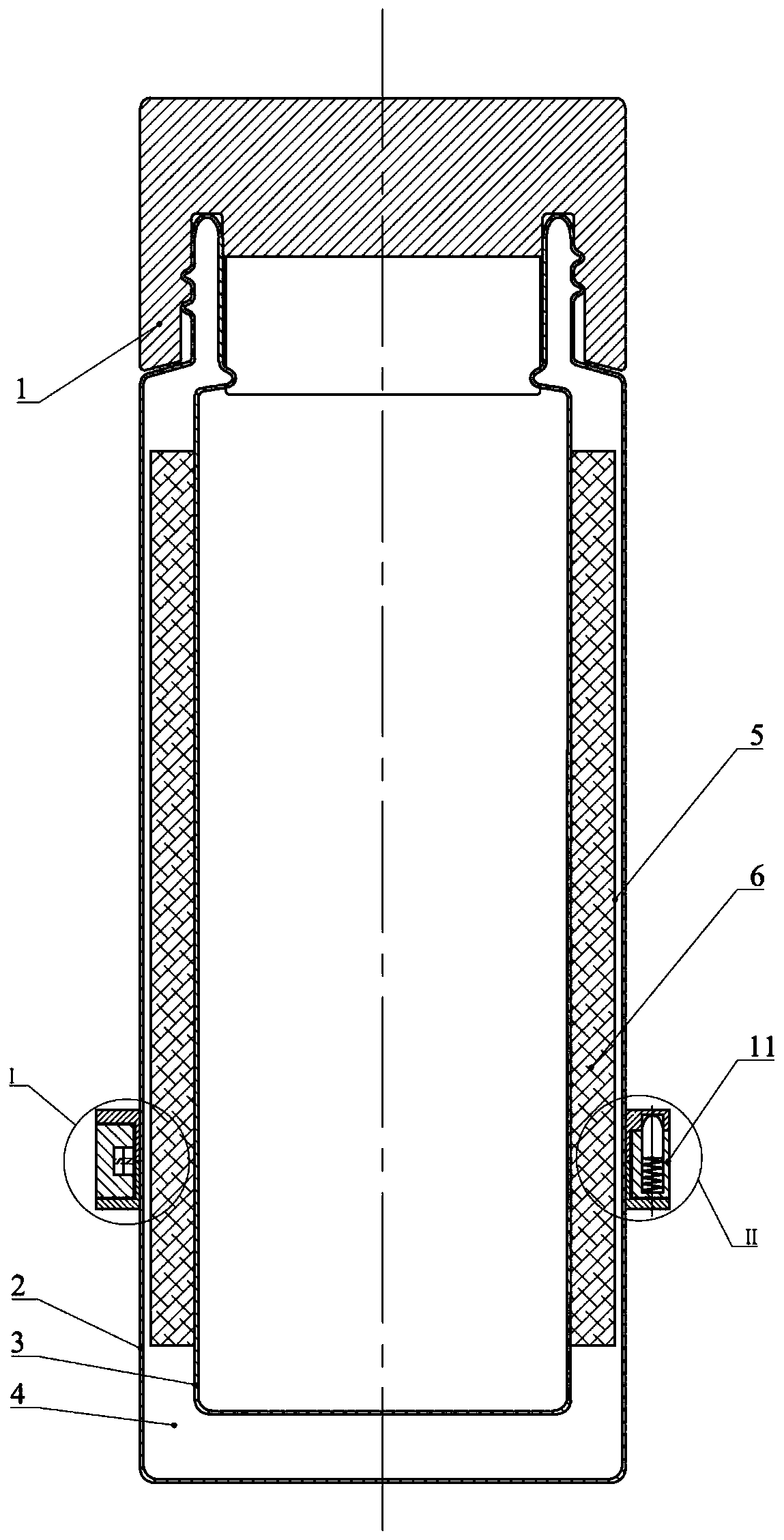
[0044] exist figure 1 and Figure 4 Among them, the phase change heat storage quick cooling temperature control cup of the present invention includes a cup body, multiple sets of phase change heat conduction structures and control switches. The cup body comprises a cup cover (1), an inner container (3) and an outer container (2), and a vacuum cavity (4) is formed between the inner container (3) and the outer container (2).

[0045]In this example, the multi-group phase-change heat-conducting structures include four groups, which are uniformly arranged in the vacuum chamber, and each group includes an arc-shaped heat-conducting shell (5), a phase-change material (6), a heat-conducting sheet (14) and a limiting sheet (15) , the phase change material (6) is encapsulated in the arc-shaped heat-conducting shell (5), the arc-shaped heat-conducting shell (5) is welded on the wall of the inner tank (3), and the outer arc of the arc-shaped heat-conducting shell (5) is connected with t...

Embodiment 2

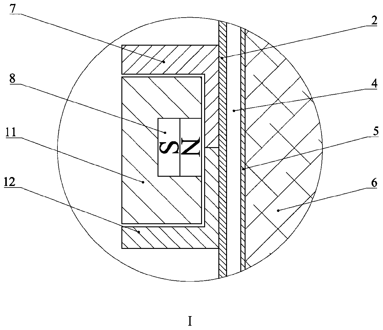
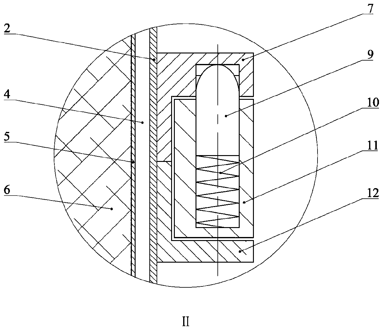
[0052] Optionally in this example, the control switch is also provided with a positioning structure, such as image 3 and Figure 7 As shown, it includes an upper fixing ring (7), a lower fixing ring (12) and a bullet buckle (9). Between the upper and lower fixing rings, the bullet buckle (9) is installed on the adjustment ring (11) through the compression spring (10), and is connected with the heat preservation position hole (17) and the heat dissipation position on the upper fixing ring (7) respectively. The location hole (18) locates the connection. Such as Figure 7 As shown, the external magnet (8) can only be switched in these two positions by the heat preservation position hole (17) and the heat dissipation position hole (18). The two positions are respectively used for the positioning of the adjusting ring in the two situations of heat dissipation and heat preservation.

Embodiment 3

[0054] This instance optionally, such as Figure 4 and Figure 6 As shown, the heat conduction sheet (14) is arc-shaped to match the shape of the outer container (2), and is a strip-shaped metal sheet, which adopts an elastic material with better thermal conductivity. The heat conduction sheet (14) and the outer container (2) When in contact state, the heat conducting sheet (14) will be close to the arc of the outer bladder (2).

[0055] The heat conduction sheet (14) can make the heat conduction sheet (14) and the outer bladder (2) in a state of separation or contact through the action of the inner magnet (16) and the outer magnet (8).

[0056] The limiting sheet (15) is fixed on the inner container (3), and its position corresponds to abutting against the middle end or near the end of the heat conducting sheet (14).


PUM


Abstract

The invention relates to a phase change heat accumulation fast cooling temperature control cup, which comprises a cup body, wherein the cup body is provided with a cup cover (1), an inner liner (3) and an outer liner (2), wherein a vacuum cavity (4) is formed between the inner liner (3) and the outer liner (2); the temperature control cup also comprises a plurality of groups of phase change heat conduction structures and a control switch; the plurality of groups of phase change heat conduction structures are uniformly arranged in the vacuum cavity, and comprise arc-shaped heat conduction cases(5), phase change materials (6), heat conduction sheets (14) and position limiting sheets (15); the control switch is arranged at the bottom of the cup body, and comprises inner and outer magnet groups in paired configuration and a regulating ring (11); in a heat radiation state, the regulating ring (11) rotates, so that magnetic poles of the inner and outer magnets become different to mutually attract; the inner magnet (16) drives the heat conduction sheet (14) to be in contact with the outer liner (2) for heat radiation; when the temperature in the cup is too high, the arc-shaped heat conduction case (5) is heated to expand and is in contact with the outer liner (2) for transmitting the heat out of the cup; in the heat insulation state, the regulating ring (11) rotates, so that the magnetic poles of the inner and outer magnets become identical to repellent mutually; the inner magnet (16) drives the heat conduction sheet (14) to be separated from the outer liner (2) for heat insulation. The cup can be used for fast cooling, and can also maintain the temperature at the value suitable for drinking for a long time.

Description

technical field [0001] The invention relates to a temperature-controlled cup, in particular to a temperature-controlled cup with rapid cooling and controllable thermal insulation. Background technique [0002] The thermos cups currently on the market are generally water containers made of ceramics or stainless steel plus a vacuum layer. There is a cover on the top and the seal is tight. The purpose is to minimize heat loss and achieve heat preservation. To reduce heat loss, it is necessary to consider the three basic ways of heat transfer, namely heat conduction, heat convection and heat radiation. [0003] (1) Heat conduction: When there is no relative displacement between parts of an object or direct contact between different objects, the heat transfer generated by the thermal motion of molecules, atoms, free electrons and other microscopic particles of the substance is called heat conduction (heat conduction), Theoretically speaking, heat conduction can be carried out in...

Claims


Application Information

Patent Timeline
Patent Type & Authority Applications(China)
IPC IPC(8): A47G19/22
CPCA47G19/2288
Inventor 邵春雷谢聪刘振冉茂菁
Owner NANJING UNIV OF TECH
Learn More